Pneumatic brake

A technology of pneumatic brakes and brake pads, applied in the direction of brake types, brake components, brake actuators, etc., can solve problems such as untimely braking of high-speed pipe stranding machines, and achieve improved braking effect, improved operating life, and ease of The effect of braking delay

Active Publication Date: 2014-06-25
广东华劲汽车零部件制造有限公司
View PDF7 Cites 4 Cited by
  • Summary
  • Abstract
  • Description
  • Claims
  • Application Information

AI Technical Summary

Problems solved by technology

[0003] The purpose of the present invention is to overcome the deficiencies of the above-mentioned prior art, and provide a pneumatic brake for parking the high-speed pipe winch, which solves the problem that the brake of the high-speed pipe winch in the prior art is not timely

Method used


Image

  • Pneumatic brake

Examples


Embodiment

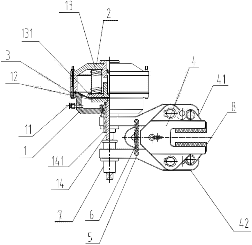
[0016] Such as figure 1 As shown, the pneumatic brake includes a cylinder block 1 and a cylinder head 2, an air source interface 11 is provided on the cylinder block 1, a pressure plate 12 and a compression spring 13 are installed in the cylinder block 1, and a spring top plate is connected to the compression spring 13 131, a sealing sheet 3 is provided between the pressure plate 12 and the spring top plate 131; a sleeve 14 is also connected to the lower end of the cylinder block 1, and a push rod 141 is arranged inside the sleeve 14, wherein the sleeve 14 is fixed On the cylinder block 1, the push rod 141 can move up and down in the sleeve 14; the other end of the sleeve 14 is fixed on the brake frame 4, and the brake frame 4 includes an upper brake pad 41 and a lower brake pad 42. Two brake screws 5 are respectively fixed on the upper brake pad 41 and the lower brake pad 42, and a brake spring 6 is clamped between the upper and lower brake screws 5, wherein the lower brake p...


PUM


Abstract

The invention discloses a pneumatic brake. The pneumatic brake comprises an air cylinder base and an air cylinder cover, wherein the air cylinder base is provided with an air source interface; a pressing plate and a compression spring are installed in the air cylinder base; the compression spring is connected with a spring ejector plate; a sealing sheet is arranged between the pressing plate and the spring ejector plate; the lower end of the air cylinder base is connected with a sleeve; an ejector rod is arranged inside the sleeve; the sleeve is fixed to the air cylinder base; the other end of the sleeve is fixed to a brake frame; the brake frame comprises an upper brake block and a lower brake block; two brake screws are fixed to the upper brake block and the lower brake block respectively; a brake spring is arranged between the upper brake screw and the lower brake screw. An air source is utilized for accurately controlling the upper brake block and the lower brake block to be folded and unfolded, so that a high-speed tubular strander brakes, and the effect of shutting down the tubular strander immediately is achieved.

Description

technical field [0001] The invention relates to a brake, in particular to a pneumatic brake applied to a high-speed pipe stranding machine. Background technique [0002] Our country is a big manufacturing country, and all kinds of manufacturing industries are inseparable from electricity. Under the current technological level, the transmission of electricity can only be completed through various wires of different specifications. At present, the preparation of wires is relatively mature. However, how to package, store and transport the wires after the wire preparation was completed was a difficult problem in the past, until the birth of various stranding machines, such as large-scale frame stranding machines, high-speed tube stranding machines, etc. Production, packaging, storage and transportation have all brought about qualitative leaps. High-speed rotary tube stranding machine is a kind of equipment for twisting copper strands, aluminum strands, steel-cored aluminum stra...

Claims


Application Information

Patent Timeline
Patent Type & Authority Applications(China)
IPC IPC(8): F16D65/14F16D65/46F16D65/092F16D121/02
Inventor 赵东顺
Owner 广东华劲汽车零部件制造有限公司
Why Eureka
Try Eureka