Supercharge Your Innovation With Domain-Expert AI Agents!

Detachable laminated plate heat exchanger

A heat exchanger, flat-stacked technology, which is applied in the field of micro-plate heat exchangers, can solve the problems of inability to remove inner cavity fouling through maintenance and maintenance measures, short service life of flat-stacked plate heat exchangers, and poor flow of heat exchange medium. Smooth and other problems, to achieve the effect of simple detachable structure, high production efficiency and easy maintenance

Inactive Publication Date: 2014-06-25
JIANGSU SHUGUANG PRESSURE VESSEL
View PDF3 Cites 1 Cited by
  • Summary
  • Abstract
  • Description
  • Claims
  • Application Information

AI Technical Summary

Problems solved by technology

However, after the flat-stacked plate heat exchanger in the prior art is used for a period of time, it is inevitable that no scale will accumulate between the heat exchange plates.
Once the inner cavity of the flat-stacked plate heat exchanger with this overall structure is scaled, it cannot be effectively removed. The gradually accumulated scale will inevitably reduce the volume of the inner cavity, resulting in poor flow of the heat exchange medium and directly reducing the heat exchange efficiency.
The prior art product is an integral structure, and the stacked heat exchange plates cannot be disassembled, and the inner chamber fouling cannot be removed through maintenance and maintenance measures, resulting in practical problems such as a short service life of the flat-stacked plate heat exchanger and high supporting costs.

Method used


Image

  • Detachable laminated plate heat exchanger
  • Detachable laminated plate heat exchanger

Examples


Embodiment Construction

[0013] The present invention will be further described below according to the accompanying drawings and in conjunction with the embodiments.

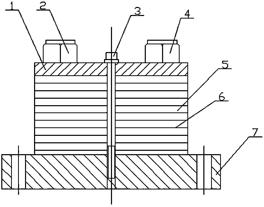
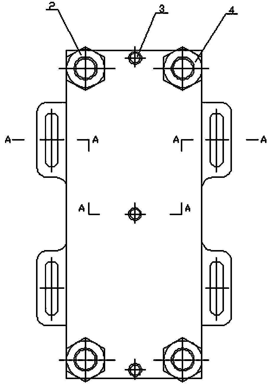
[0014] figure 1 Shown is a detachable flat-stack heat exchanger, example for use in the petrochemical industry. The heat exchange medium is oil-water. It includes a pressure plate 1, an inlet joint 2, a bolt 3, an outlet joint 4, a heat exchange plate 5, a sealing strip 6 and a bottom plate 7. The pressing plate 1 is located on the top layer, and it is a rectangular plate with screw holes communicating with the passages of the heat exchange plate 5 at the four corners. The inlet joint 2 and the outlet joint 4 are both threaded joints with built-in through holes, which are respectively paired and screwed into the screw holes at the four corners of the pressure plate 1 to prepare for introducing the heat exchange medium and the heat exchange medium respectively. The base plate 7 is a flat plate supporting the pressing plate 1, and is a...


PUM


Abstract

The invention discloses a detachable laminated plate heat exchanger which comprises a pressing plate, inlet connectors, a bolt, outlet connectors, heat exchange plates, sealing strips and a bottom plate. The outer edges of the laminated heat exchange plates are spaced through the sealing strips to form a double-face sealing pair, 3-5 through holes are formed in the plate surface longitudinal central axis of the pressing plate and the heat exchange plates at equal intervals, screw holes matched with the bolt are formed in the upward plate surface, corresponding to the through holes in the pressing plate, of the bottom plate, the pressing plate is arranged on the top-layer heat exchange plate, and the bolt penetrates through the through holes in the pressing plate and the through holes in the heat exchange plates to be directly matched with a screw hole preset in the bottom plate to form a detachable structure. After the heat exchanger is used for a period of time, dirt consequentially accumulates inside the heat exchanger, heat exchange efficiency decreases, a user can detach parts to maintain the heat exchanger correspondingly, disassembly, dirt cleaning and contaminant release are easy and thorough, original heat exchange efficiency can be maintained after reinstallation. After the heat exchanger is disassembled, if a certain heat exchange plate is damaged, targeted replacement can be carried out, and therefore matching cost of the user is lowered.

Description

technical field [0001] The invention relates to a heat exchange device, in particular to a plate heat exchanger, in particular to a detachable miniature plate heat exchanger. Background technique [0002] The flat-stacked plate heat exchanger is a structural type of small-scale heat exchanger. Its structural characteristics are mainly reflected in the small area of ​​the single heat exchange plate, the thin heat exchange plate, the large number of flat stacked layers, and the surrounding area between the heat exchange plates. Sealing and connection are achieved by brazing. The heat exchanger with this overall structure has good sealing performance, reliable connection, small size and high heat exchange efficiency, and can fully meet the set heat exchange requirements. However, after the flat-stacked plate heat exchanger in the prior art is used for a period of time, it is inevitable that no scale will accumulate between the heat exchange plates. Once the inner cavity of th...

Claims


Application Information

Patent Timeline
IPC IPC(8): F28D9/00F28F9/26F28F11/02
Inventor 蒋存明张震宁
Owner JIANGSU SHUGUANG PRESSURE VESSEL
Features
  • R&D
  • Intellectual Property
  • Life Sciences
  • Materials
  • Tech Scout
  • Unparalleled Data Quality
  • Higher Quality Content
  • 60% Fewer Hallucinations
Learn More