
A Comprehensive Correction Method for Geometric Angle Error of Laser Tracker

A laser tracker, angle error technology, applied in instruments, optical devices, measuring devices, etc., can solve the problem of lack of tracker geometric structure angle error, etc., and achieve the effects of good real-time performance, high precision, and easy implementation.

Active Publication Date: 2019-09-27
INST OF MICROELECTRONICS CHINESE ACAD OF SCI
View PDF4 Cites 0 Cited by
  • Summary
  • Abstract
  • Description
  • Claims
  • Application Information

AI Technical Summary

Problems solved by technology

The existing tracker error correction methods lack a comprehensive correction method for the tracker geometric structure angle error

Method used


Image

  • A Comprehensive Correction Method for Geometric Angle Error of Laser Tracker
  • A Comprehensive Correction Method for Geometric Angle Error of Laser Tracker
  • A Comprehensive Correction Method for Geometric Angle Error of Laser Tracker

Examples


Embodiment Construction

[0018] The technical solutions in the embodiments of the present invention will be accurately and completely described below in conjunction with the accompanying drawings in the embodiments of the present invention. Obviously, the described embodiments are only some, not all, embodiments of the present invention. Based on this, all other embodiments obtained by persons of ordinary skill in the art without making creative efforts belong to the protection scope of the present invention.

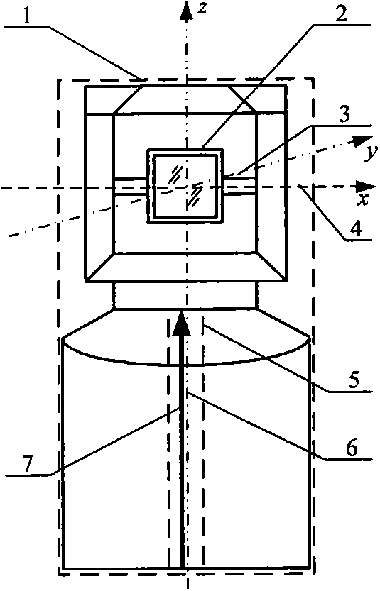
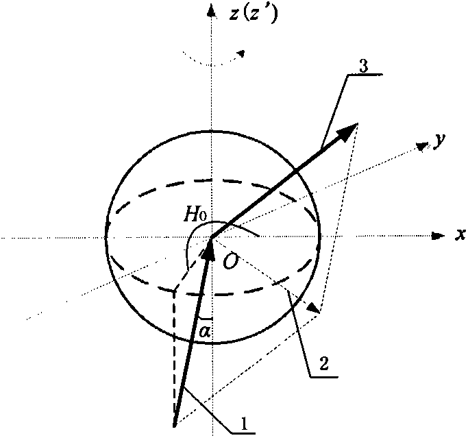
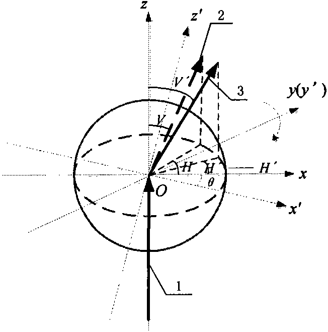
[0019] The method for correcting the angle error of the geometric structure of the tracker involved in the present invention establishes a comprehensive model of the angle error between the horizontal axis and the vertical axis, the optical axis and the vertical axis, and the tracking mirror and the horizontal axis of the tracker, and uses the method of coordinate conversion to simulate tracking According to the influence of the actual angle error of the tracker on the measurement results, the a...


PUM


Abstract

The invention discloses a method for comprehensively correcting a geometric angle error of a laser tracker. The method is mainly used for error compensation and accuracy increase in the manufacture and use processes of a measurement system of the laser tracker. According to the structure, the laser tracker comprises a cross shaft, a vertical shaft, a polish shaft, a tracking reflecting rotating mirror and the like. A strict geometric position relation of the cross shaft, the vertical shaft, the polish shaft, the tracking reflecting rotating mirror and the like must be guaranteed. However, in the manufacture, installation, transportation and use processes, the strict geometric position relation of the components is difficult to guarantee, so that the final coordinate measurement accuracy of the tracker is influenced. Thus, a geometric structure error of the components needs to be corrected. The method for comprehensively correcting the geometric structure angle error of the tracker is not available in an existing tracker error correction method. Thus, the complete method for angular correction is created, so that comprehensive compensation is conducted on the geometric angle error of the tracker.

Description

technical field [0001] The invention relates to a method for comprehensively correcting geometric angle errors of a laser tracker, which is mainly used for error compensation and precision improvement in the process of manufacturing and using a laser tracker measurement system. Background technique [0002] The structure of the laser tracker includes horizontal axis, vertical axis, optical axis and tracking mirror, etc., all of which must ensure strict geometric positional relationship. However, in the process of manufacturing, installation, handling and use, it is difficult to guarantee the strict geometric positional relationship between the above components, thus affecting the final coordinate measurement accuracy of the tracker. Therefore, it is necessary to correct the geometric structure errors of the above-mentioned components. The existing tracker error correction methods lack a comprehensive correction method for the tracker geometric structure angle error. In vie...

Claims


Application Information

Patent Timeline
Patent Type & Authority Patents(China)
IPC IPC(8): G01B11/00
Inventor 周维虎张滋黎劳达宝袁江纪荣祎董登峰刘鑫朱涵李万红
Owner INST OF MICROELECTRONICS CHINESE ACAD OF SCI
Learn More