Slender rod bi-directional internal force measuring sensor and calibration method

A technology for measuring sensors and thin rods, which is applied in the direction of measuring force, force/torque/power measuring instrument calibration/testing, measuring devices, etc. It can solve the problems of wide versatility, high precision, high stability, etc., and achieve good repeatability , Wide versatility, non-destructive effect on measurement accuracy

Active Publication Date: 2014-06-25
SOUTHEAST UNIV
View PDF7 Cites 7 Cited by
  • Summary
  • Abstract
  • Description
  • Claims
  • Application Information

AI Technical Summary

Problems solved by technology

[0004] Technical problem to be solved: Aiming at the deficiencies of the existing technology, the present invention proposes a thin-rod two-way inner inner detection sensor and a calibration method to solve the problem that the various rod internal force measurement methods in the prior art cannot simultaneously meet the requirements of non-destructive measurement, high precision and Technical issues with high stability and wide versatility

Method used


Image

  • Slender rod bi-directional internal force measuring sensor and calibration method
  • Slender rod bi-directional internal force measuring sensor and calibration method
  • Slender rod bi-directional internal force measuring sensor and calibration method

Examples


Embodiment Construction

[0021] The present invention will be further described below in conjunction with the accompanying drawings.

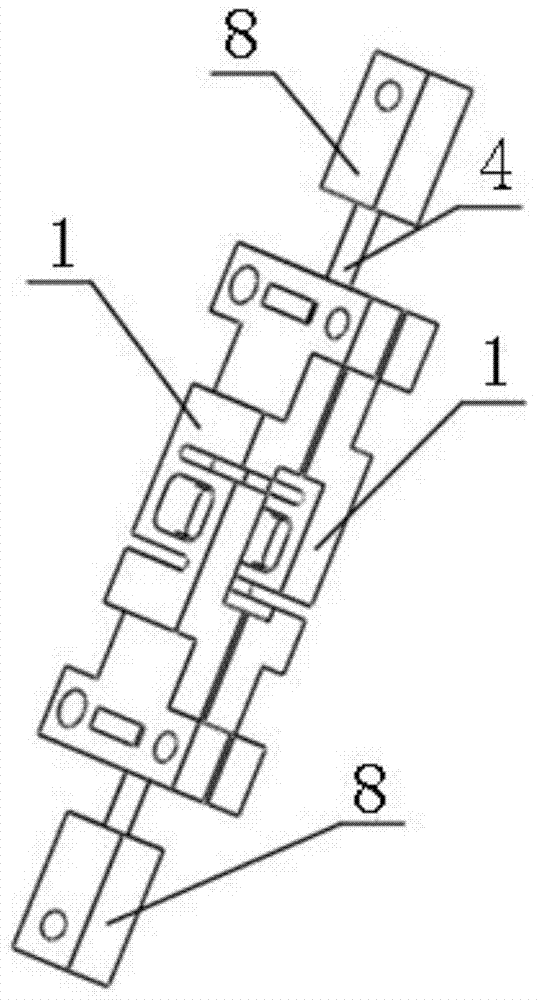
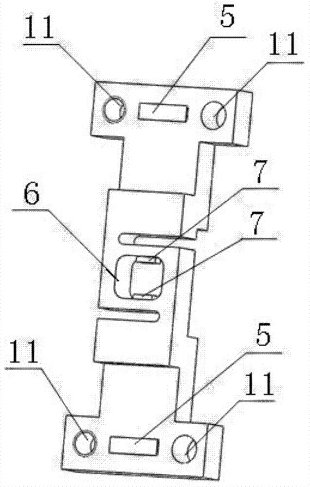
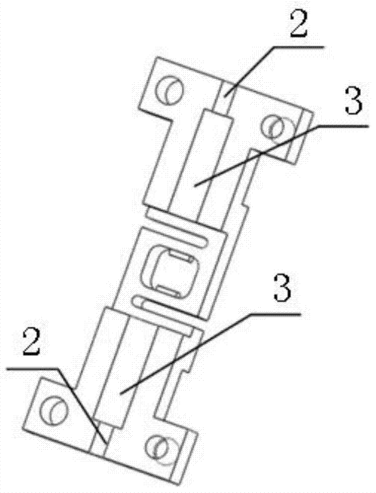
[0022] Such as Figure 1 to Figure 3 As shown, a thin-rod two-way internal force measurement sensor includes two identical symmetrically arranged splints 1, four mounting holes 11 are respectively arranged on the two splints 1, bolts are arranged in the mounting holes 11, and each splint 1 There are 2 card slots 2 and 2 grooves 3 on the back, such as image 3 As shown, the card slot 2 and the groove 3 are on a straight line, and the groove 3 is located between the two card slots 2, the card slot 2 is adapted to the thin rod 4, and the size of the groove 3 is relatively large. The thin rod 4 is stuck in the two card slots 2, and the rod body between the two card slots 2 passes through the groove 3 without contacting the groove 3; the two splints 1 are connected back to back by bolts Fixed together, the distance between the two splints 1 can be adjusted by changing the...


PUM


Abstract

The invention discloses a slender rod bi-directional internal force measuring sensor which comprises two identical clamping plates which are arranged symmetrically. The two clamping plates are fixed together in a back to back mode, the distance between the two clamping plates is adjustable, and a clearance is reserved between the two clamping plates. Clamping grooves and grooves are formed in the back face of each clamping plate, the clamping grooves and the grooves are formed in the same straight line, the clamping grooves are matched with slender rods, and the slender rods are clamped in the clamping grooves and penetrate through the grooves without making contact with the grooves. The front face of each clamping plate is provided with pressure measuring units, and the position of each pressure measuring unit is opposite to the corresponding clamping grooves. Tension and pressure measuring holes are further formed in the positions, opposite to the grooves, of each clamping plate, and tension and pressure measuring devices are arranged on the inner walls of the tension and pressure measuring holes. Under the condition that the clamping force of the slender rods is not changed, the pressure and the tension borne by the slender rods in the axial direction are measured in multiple angles, and the pressure and the tension are finally expressed into a relational expression between force and voltages, and when the slender rod bi-directional internal force measuring sensor is put into actual use, the size of the internal force of the slender rods to be measured can be reflected simply by reading corresponding voltages.

Description

technical field [0001] The invention relates to the field of non-destructive testing of force, in particular to a sensor and a calibration method suitable for testing internal force of thin rods. Background technique [0002] In modern engineering, it is necessary to use a large number of rods to form the frame of the equipment. This structure has the advantages of stability and light weight. The tension and pressure received are detected to determine the force value of the rod in the equipment. In order to accurately understand the actual state of the rod in the equipment, it is necessary to select appropriate measuring equipment and measuring methods. [0003] Today, the internal force measurement methods used in engineering mainly include (1) strain gauge method; (2) magnetic flux method; (3) frequency method. In the strain gauge method, strain gauges are pasted on the rods to be measured. This method needs to paste strain gauges on each rod, which requires a lot of man...

Claims


Application Information

Patent Timeline
IPC IPC(8): G01L1/22G01L25/00
Inventor 宋爱国潘栋成李会军
Owner SOUTHEAST UNIV
Why Eureka
Try Eureka