
A test method for a thin-walled cylindrical shell member vibration test system

A thin-walled cylinder and vibration testing technology, which is applied in the testing of machines/structural components, vibration testing, measuring devices, etc., can solve problems such as difficulties, low measurement efficiency, and low measurement stability, and achieve high measurement efficiency and stable measurement sex high effect

Active Publication Date: 2016-04-06
NORTHEASTERN UNIV LIAONING
View PDF6 Cites 0 Cited by
  • Summary
  • Abstract
  • Description
  • Claims
  • Application Information

AI Technical Summary

Problems solved by technology

[0003] At this stage, laser Doppler vibrometers are often used to perform vibration tests on these thin-walled cylindrical shell components, but this method of vibration measurement has obvious shortcomings when facing thin-walled cylindrical shell components
First of all, it is difficult for the laser Doppler vibrometer to perform 360° circumferential measurement of thin-walled cylindrical shell components, so it is even more difficult to achieve full-field measurement and frequency response function measurement; secondly, it is difficult to guarantee The laser emitted by the laser Doppler vibrometer can be vertically incident on the outer surface of the thin-walled cylindrical shell member, resulting in low measurement efficiency and low measurement stability

Method used


Image

  • A test method for a thin-walled cylindrical shell member vibration test system
  • A test method for a thin-walled cylindrical shell member vibration test system
  • A test method for a thin-walled cylindrical shell member vibration test system

Examples


Embodiment Construction

[0034] The present invention will be further described in detail below in conjunction with the accompanying drawings and specific embodiments.

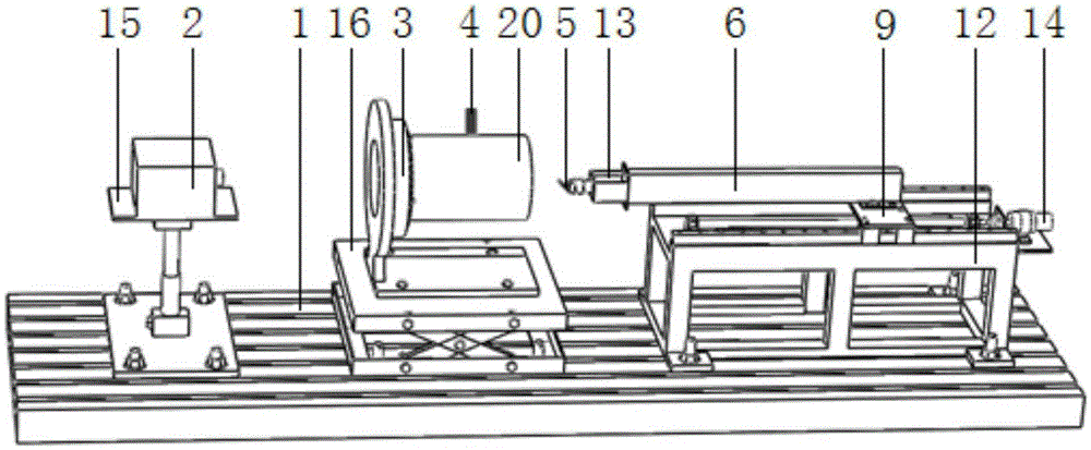
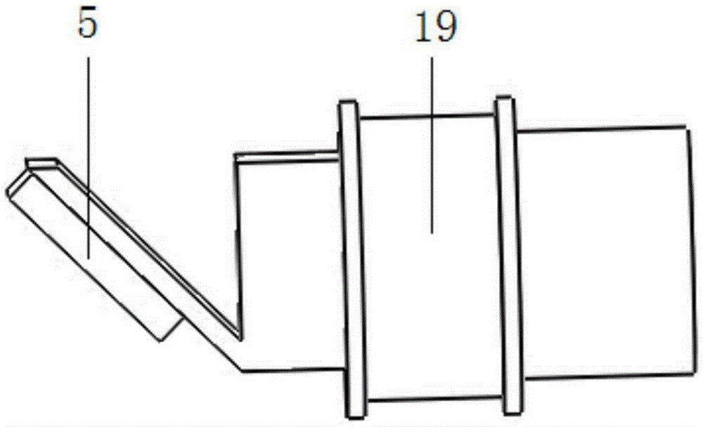
[0035] Such as figure 1 , 2 , 3, a thin-walled cylindrical shell component vibration testing system, including a base 1, a laser Doppler vibrometer 2, a specimen mounting table 3, a vibrator 4 and a laser reflection unit, the laser multiple The Puler vibrometer 2 is arranged on the base 1, the test piece mounting platform 3 is arranged on the base 1, and the laser emitting end of the laser Doppler vibrometer 2 corresponds to the test piece mounting platform 3; The vibrator 4 is located on the side of the test piece mounting table 3; the laser reflection unit is arranged on the base 1 through a fixed bracket 12;

[0036] The laser reflection unit includes a reflector 5 and a transmission part. The transmission part includes a guide rail 11, a slider 10, a sliding plate 9, a lead screw 8, a screw nut 7 and a measuring arm 6. The guide...


PUM


Abstract

The invention relates to a vibration testing system and method for a thin-wall cylindrical shell component, and belongs to the technical field of laser Doppler vibration measurement. A laser Doppler vibrometer, a test piece mounting table and a laser reflecting unit are all arranged on a base, and the laser emitting end of the laser Doppler vibrometer corresponds to the test piece mounting table. Guide rails and a lead screw of the laser reflecting unit are both fixedly arranged on a fixing support, sliding blocks are fixedly arranged on a sliding carriage, and the sliding carriage is in sliding fit with the guide rails through the sliding blocks. A nut is arranged on the lead screw in a sleeved mode, and the nut is fixedly connected to the lower surface of the sliding carriage. One end of a measurement arm is fixedly arranged on the upper surface of the sliding carriage, and the measurement arm, the lead screw and the guide rails are all arranged in parallel. A reflecting mirror is arranged at the other end of the measurement arm, a 45-degree included angle is formed between the reflecting mirror and the vertical direction, and the laser emitting end of the Doppler vibrometer corresponds to the reflecting mirror. A first drive motor is mounted between the reflecting mirror and the measurement arm, and an output shaft of the first drive motor is fixedly connected with the reflecting mirror. A second drive motor is arranged at the shaft end of the lead screw.

Description

technical field [0001] The invention belongs to the technical field of laser Doppler vibration measurement, in particular to a vibration testing system and testing method for a thin-walled cylindrical shell component based on the laser Doppler vibration measurement technology. Background technique [0002] In the field of aerospace, engine R&D and design are very important. In the process of engine R&D and design, vibration testing of engine parts is an important part, and engine parts also contain a large number of thin-walled cylindrical shell components , such as engine casings, etc., relevant technical personnel need to perform vibration tests on these thin-walled cylindrical shell components to obtain the relevant vibration characteristics of the thin-walled cylindrical shell components. [0003] At this stage, laser Doppler vibrometers are often used to perform vibration tests on these thin-walled cylindrical shell components, but this method of vibration measurement h...

Claims


Application Information

Patent Timeline
Patent Type & Authority Patents(China)
IPC IPC(8): G01M7/02
Inventor 罗忠于长帅王菲于清文朱云鹏
Owner NORTHEASTERN UNIV LIAONING
Learn More