
Distribution network fault distance measurement method based on fault transient state traveling wave zero-mode and aerial-mode speed difference

A transient traveling wave, fault location technology, applied in the fault location and other directions, can solve the problems of poor timeliness, low accuracy, and small scope of application, and achieve the effect of high accuracy, good timeliness, and large scope of application

Inactive Publication Date: 2014-06-25
STATE GRID CORP OF CHINA +1
View PDF2 Cites 37 Cited by
  • Summary
  • Abstract
  • Description
  • Claims
  • Application Information

AI Technical Summary

Problems solved by technology

[0006] In the process of realizing the present invention, the inventor found that there are at least defects such as small application range, poor timeliness and low accuracy in the prior art

Method used


Image

  • Distribution network fault distance measurement method based on fault transient state traveling wave zero-mode and aerial-mode speed difference
  • Distribution network fault distance measurement method based on fault transient state traveling wave zero-mode and aerial-mode speed difference
  • Distribution network fault distance measurement method based on fault transient state traveling wave zero-mode and aerial-mode speed difference

Examples


Embodiment Construction

[0033] The preferred embodiments of the present invention will be described below in conjunction with the accompanying drawings. It should be understood that the preferred embodiments described here are only used to illustrate and explain the present invention, and are not intended to limit the present invention.

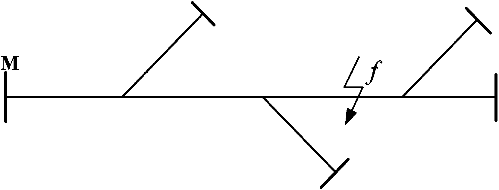
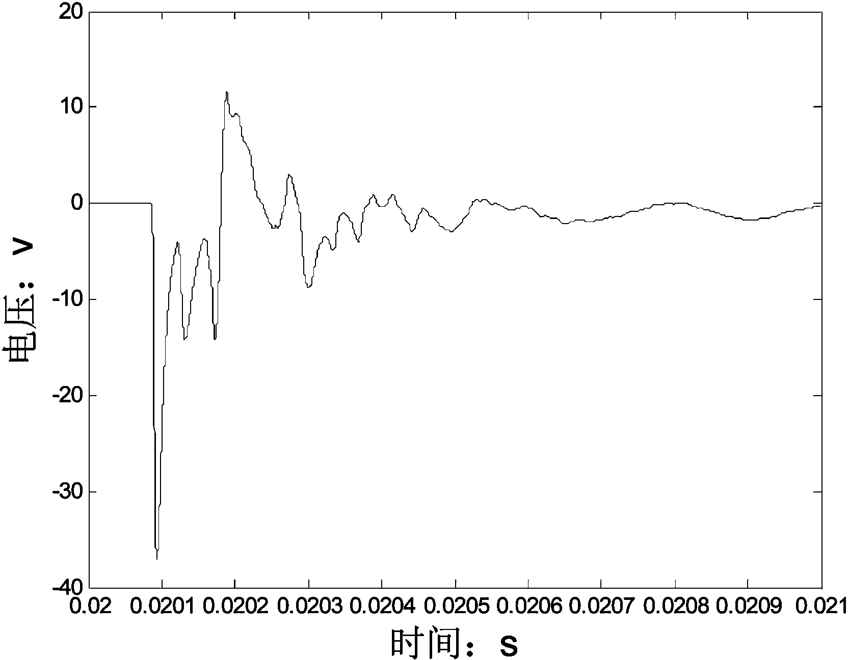
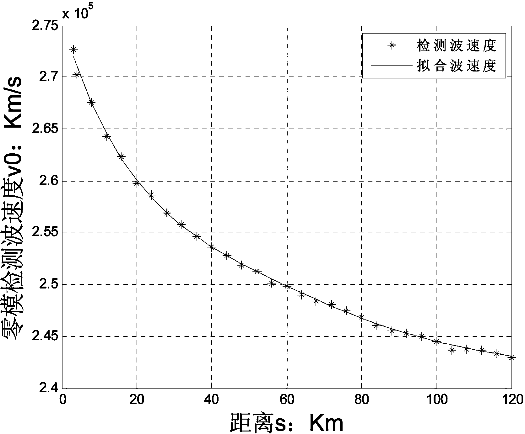
[0034] According to an embodiment of the present invention, such as figure 1 , figure 2 and image 3 As shown, a distribution network fault location method based on the speed difference between fault transient traveling wave zero-mode and line-mode is provided, which provides a simple operation, can adapt to the characteristics of complex distribution network structure with many branches, and has certain anti-interference A single-ended traveling wave fault location method that meets the positioning accuracy requirements. The distribution network fault location method based on the fault transient traveling wave zero-mode and line-mode speed difference is a single...


PUM


Abstract

The invention discloses a distribution network fault distance measurement method based on a fault transient state traveling wave zero-mode and aerial-mode speed difference. The method mainly includes the steps that the arrival moment t1 of an aerial-mode wave head and the arrival moment t0 of a zero-mode wave head are marked respectively, and the difference delta t of the time used for a zero-mode traveling wave to arrive at a measurement end and the time used for an aerial-mode traveling wave to arrive at the measurement end is obtained in a calculated mode; a typical fault distance is set to be Sk in a simulation or on-site test, the moment t0k at which the zero-mode wave head arrives at a measurement point is recorded, the speed v0k of the zero-mode traveling wave corresponding to the fault distance Sk is obtained, and a set of data related to the corresponding relationship between fault distances S and zero-mode detection wave speeds are obtained; by means of an obtained analytical expression, an iterative formula of the fault distance is obtained, and the corresponding fault distance is solved. According to the distribution network fault distance measurement method based on the fault transient state traveling wave zero-mode and aerial-mode speed difference, the defects that the application range is small, timeliness is poor and accuracy is low in the prior art can be overcome, and the method has the advantages of being large in application range, good in timeliness and high in accuracy.

Description

technical field [0001] The invention relates to the technical field of power grid detection, in particular to a distribution network fault location method based on the speed difference between fault transient traveling wave zero-mode and line-mode. Background technique [0002] At present, there are two main types of traveling wave methods for single-phase ground fault location in distribution networks, one is the method of injecting diagnostic signals at the head end; the other is the method of distance measurement using the electrical characteristics of the transient component of the fault signal. This method is less affected by transformer saturation, fault initial phase angle, fault resistance and system operation mode, and has become a research hotspot in recent years. The ranging method using the electrical characteristics of the transient component of the fault signal can be further divided into single-ended (Type A) traveling wave method and double-ended (Type B) tra...

Claims


Application Information

Patent Timeline
IPC IPC(8): G01R31/08
Inventor 韩晓言刘朕志舒勤董丽梅
Owner STATE GRID CORP OF CHINA
Learn More