
Nail-carrying disc structure of circumcision stapler

A technology of suture staples and staplers, which is applied in the field of medical surgical instruments, can solve the problems of long staple removal time, troublesome staple removal, and increased work intensity of medical staff, so as to prevent infection and reduce operation intensity.

Active Publication Date: 2016-01-20
苏州维尔蒙医疗器械有限公司
View PDF9 Cites 0 Cited by
  • Summary
  • Abstract
  • Description
  • Claims
  • Application Information

AI Technical Summary

Problems solved by technology

[0004] It is not limited to the nail-carrying tray of the above-mentioned circumcision stapler because the structure is unreasonable and there are the following technical problems in actual use: the first is that it is troublesome to take off the nail after the wound is healed; The skin at the site will be stubbornly combined with the staples as a whole and even wrap the staples as a whole, so when removing the staples with the staple remover, the pain of the patient will be aggravated, and even bleeding and infection will be caused.
If in order to reduce the degree of damage to the wound skin 2 as much as possible, the time spent on removing the staples by the medical staff will inevitably be lengthy, and the work intensity of the medical staff will increase.

Method used


Image

  • Nail-carrying disc structure of circumcision stapler
  • Nail-carrying disc structure of circumcision stapler
  • Nail-carrying disc structure of circumcision stapler

Examples


Embodiment 1

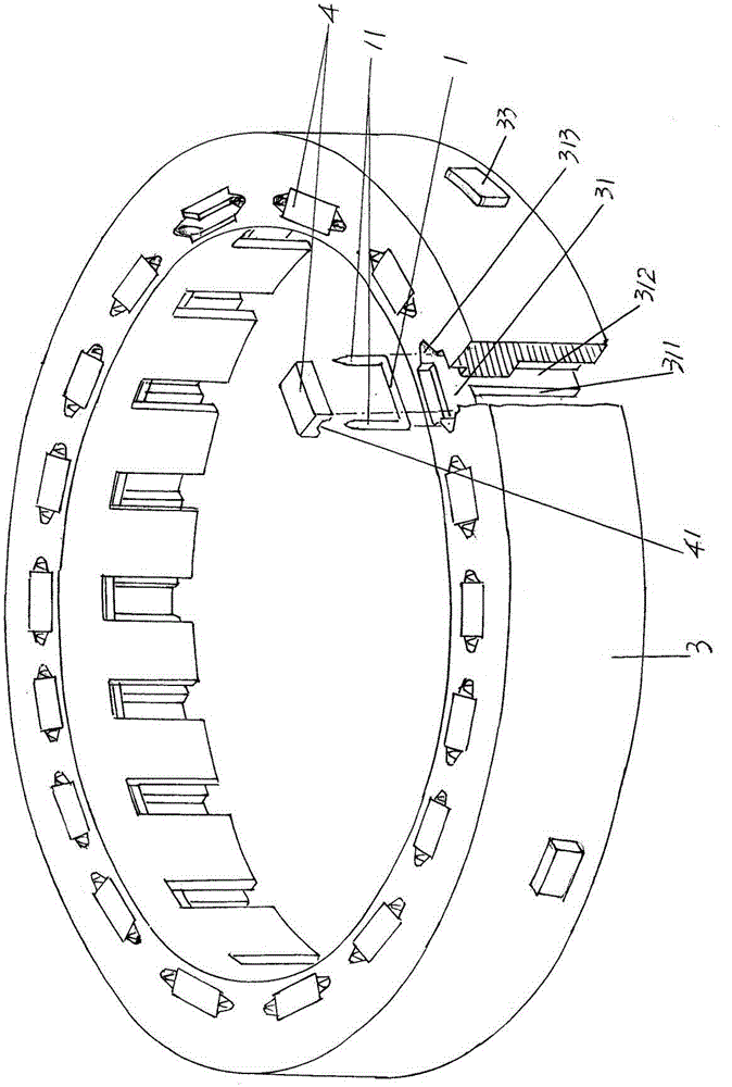
[0029] See figure 1 , provides a nail-loaded tray body 3, the overall shape of the nail-loaded tray body 3 is in the shape of a ring, and preferably plastic molding is used, on the nail-loaded tray body 3 and around the nail-loaded tray body 3 The circumferential direction of the nail loading chamber 31 is formed in a spaced state, and the nail loading chamber 31 penetrates from the upward side of the nail loading tray body 3 to the downward facing side, that is to say, from the height direction of the nail loading tray body 3 side ( figure 1 The upper side of the position state shown) through to the other side ( figure 1 The lower side of the shown position state), and the staple 1 is accommodated in the nail-carrying cavity 31 in an inserting manner, and the staple 1 has a pair of staple feet 11 for figure 1 The position state shown is an example, with a pair of staple feet 11 facing upwards. Depend on figure 1 It can be seen from the schematic diagram that the over...

Embodiment 2

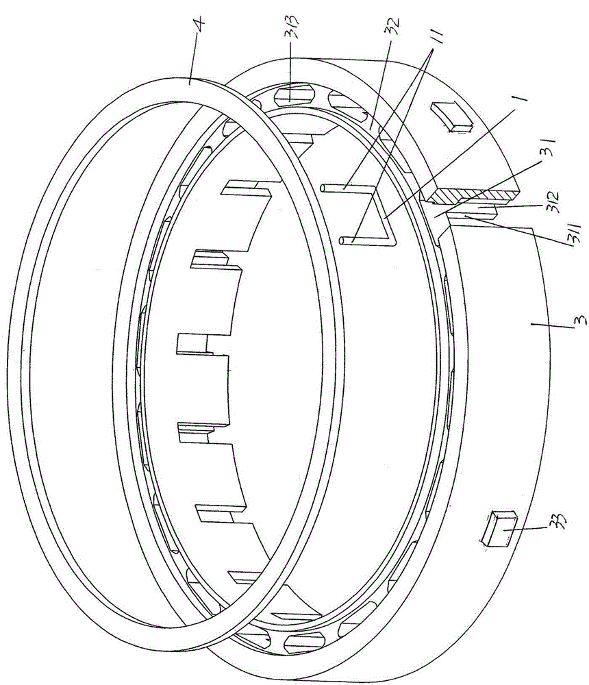
[0038] See figure 2 ,Should figure 2 Another structural form of the aforementioned staple pad 4 is shown, specifically, the structure of the staple pad 4 is an annular staple pad washer. Since the staple pad 4 is an annular staple pad washer, the upper side of the aforementioned staple tray body 3 (with figure 2 The shown position is taken as an example) and a washer groove 32 is recessed around the circumferential direction of the staple tray body 3 at a position corresponding to the nail loading cavity 31 , and the staple washer is embedded in the washer groove 32 .

[0039] In the present embodiment, the width of the aforementioned staple back washer is adapted to the width of the washer groove 32, and the thickness is adapted to the depth of the washer groove 32, for example, the width of the washer groove 32 is 3 mm, and the depth is 1 mm. , then the width of the staple pad gasket is also 3 mm, and the thickness is 1 mm. All the other are the same as the description...


PUM


Abstract

The invention belongs to the technical field of medical surgical instruments, and relates to a nail loading plate structure of a prepuce cutting stitching instrument. The nail loading plate structure comprises an annular nail loading plate body, a nail loading cavity is formed in the nail loading plate body in the circumferential direction of the nail loading plate body and contains a stitching nail, and the stitching nail is provided with a pair of stitching nail pins. The nail loading plate structure is characterized by further comprising a stitching nail cushion, and the position, corresponding to the stitching nail, of the stitching nail cushion is embedded into the side, facing upwards, of the nail loading plate body. In the process of wound skin healing, the wound skin cannot be firmly bonded with the stitching nail or wrap the stitching nail, the nail can be conveniently dismounted, the efficiency of dismounting the stitching nail is improved, and the operating intensity of medical workers can be obviously relieved. When the stitching nail is dismounted, due to the fact that a pincers opening of nail dismounting pincers is located between a nail body of the stitching nail and the stitching nail cushion, the pincers opening cannot make direct contact with the wound skin, the wound skin healed but be in the fragile state can be prevented from being hurt, and the infection cannot happen.

Description

technical field [0001] The invention belongs to the technical field of medical surgical instruments, and in particular relates to a nail-carrying disk structure of a circumcision and stapler. Background technique [0002] The aforementioned nail-loading tray can also be called a nail-loading cartridge, which is used to carry the staples for suturing the foreskin. The technical information about the circumcision stapler can be found in the published Chinese patent literature, typically such as the "circumcision stapler" recommended by the invention patent authorization announcement number CN101884559B and the "circumcision stapler" provided by CN102217969B, these two The patented solutions all have the advantages of combining the functions of cutting and suturing the foreskin to improve the progress of the operation. For details, please refer to the 33rd paragraph of the description of CN101884559B and the 38th paragraph of the description of CN102217969B. [0003] The afore...

Claims


Application Information

Patent Timeline
Patent Type & Authority Patents(China)
IPC IPC(8): A61B17/326A61B17/115
CPCA61B17/326
Inventor 朱振荣朱佳孙朴
Owner 苏州维尔蒙医疗器械有限公司
Learn More