Temperature control valve, control method thereof and medical volatilizer comprising same

A temperature control valve and temperature control technology, applied in the field of anesthesia machines, can solve problems such as changes in valve seat deformation, changes, and unstable flow control.

Inactive Publication Date: 2014-07-02
BEIJING AEONMED
View PDF5 Cites 2 Cited by
  • Summary
  • Abstract
  • Description
  • Claims
  • Application Information

AI Technical Summary

Problems solved by technology

[0015] However, the temperature compensation unit of this anesthesia vaporizer has the following defects: 1. The structure of the temperature compensation unit is complicated, it is difficult to manufacture and maintain, and the amount of consumables is large, which is not conducive to saving costs; 2. The temperature compensation unit controls the flow rate after the temperature changes. Unstable, the air resistance of the temperature compensation unit will change after long-term use, that is, the deformation of the valve seat will change when the temperature changes, which will lead to changes in the output concentration of the anesthesia vaporizer; 3. Only a part of the temperature compensation unit is immersed in the In anesthetics, the top of the valve seat and the lower valve plate are far away from the bottom of the evaporator, and the temperature compensation unit cannot accurately detect the temperature change of the anesthetic agent, resulting in inaccurate deformation of the valve seat, which in turn leads to inaccurate movement distance of the lower valve plate
[0016] Looking at the prior art volatilizers for traditional Chinese medicine (i.e. anesthesia vaporizers), the flow control of the fresh gas is unstable after the temperature of the anesthetic agent changes. The concentration of the output mixed anesthetic vapor changes. At the same time, the temperature sensing device in the temperature compensation unit or the temperature control valve is far away from the bottom of the volatilization chamber of the volatilizer, and the temperature cannot be transmitted to the temperature compensation unit or the temperature control valve in time. shortcoming

Method used


Image

  • Temperature control valve, control method thereof and medical volatilizer comprising same
  • Temperature control valve, control method thereof and medical volatilizer comprising same
  • Temperature control valve, control method thereof and medical volatilizer comprising same

Examples


Embodiment Construction

[0064] The technical solutions of the present invention will be further described below in conjunction with the accompanying drawings and through specific implementation methods.

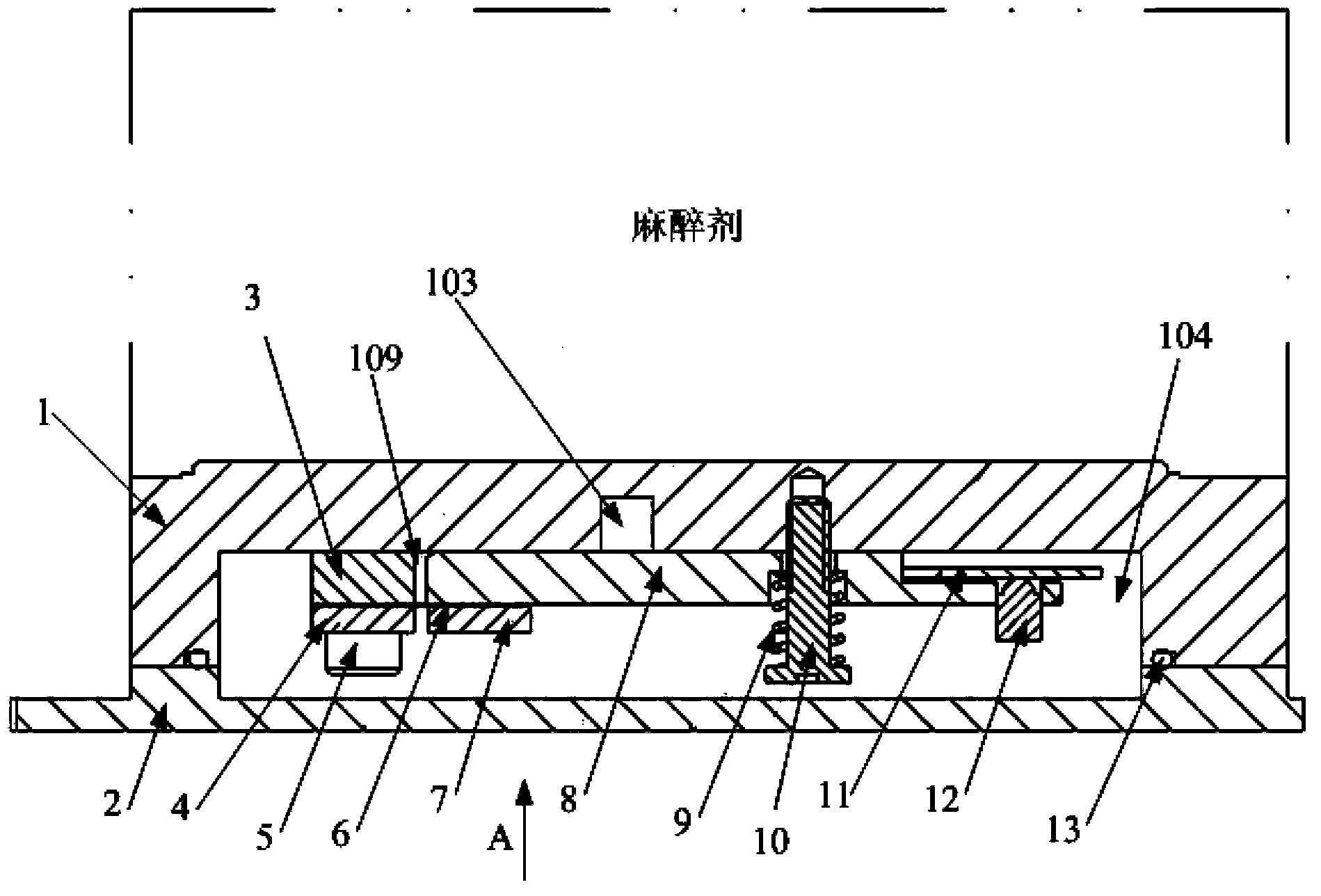
[0065] Such as Figure 3-6 As shown, the temperature control valve in this embodiment includes a tank body 1 and a cover plate 2. There is a gas channel between the tank body 1 and the cover plate 2 that accommodates the gas and allows the gas to pass through. The gas channel includes the first gas Chamber 103 and second air chamber 104, the tank body 1 comprises a sealed tank body first end 105 and an open tank body second end 106, the tank body first end 105 has a first wall surface 107 close to the tank body second end 106 and the second wall surface 108 away from the second end 106 of the tank body, the first wall surface 107 is recessed toward the second wall surface 108 to form the above-mentioned first air chamber 103, and the space enclosed between the tank body 1 and the cover plate 2 forms...


PUM


Abstract

The invention discloses a temperature control valve which comprises a tank and a cover plate. A gas passage capable of containing gas is formed between the tank and the cover plate, and a temperature control component capable of sensing temperature changing to adjust opening degree of the gas passage. The invention further discloses a medical volatilizer which comprises a volatilizing chamber. The temperature control valve is fixedly mounted at the bottom of the volatilizing chamber. The temperature control valve is disposed at the bottom of the volatilizing chamber to enable a position above the temperature control valve to be immersed by anesthetic, the temperature control valve can sense temperature changing of the anesthetic more quickly and more accurately, the temperature control component in the temperature control valve can be utilized to enable the opening degree of the gas passage to correspondingly change according to temperature changing of the anesthetic in real time, in other words, when the anesthetic is high in temperature, anesthetic steam concentration in the volatilizing chamber is high, the gas passage is large in opening degree, and a lot of fresh gas is output, otherwise, little fresh gas is output, and finally concentration of mixed anesthetic steam output by the volatilizer is enabled to be unchanged no matter how temperature of the anesthetic changes.

Description

technical field [0001] The invention relates to the technical field of anesthesia machines, in particular to a temperature control valve, a control method of the temperature control valve and a medical volatilizer including the temperature control valve. Background technique [0002] The medical vaporizer is the anesthesia vaporizer, which is a key component of the anesthesia machine. Due to the use of powerful inhaled anesthetics, its quality not only marks the level of the anesthesia machine, but also involves the safety of the patient. Therefore, when using an anesthesia machine, the anesthesia vaporizer must be carefully checked, and its output concentration should be monitored if necessary. [0003] The design principle of the anesthesia vaporizer is to adopt some reasonable structures to precisely control the concentration of the anesthetic vapor, so as to eliminate or reduce the influence of temperature, flow, pressure changes and other factors on the anesthesia vapo...

Claims


Application Information

Patent Timeline
IPC IPC(8): A61M16/20A61M16/18
Inventor 郑殿会
Owner BEIJING AEONMED
Why Eureka
Try Eureka