Glass substrate cutting equipment and cutting method

A technology for glass substrates and cutting equipment, applied in glass manufacturing equipment, glass cutting devices, optics, etc., can solve the problems of inability to meet the refined production of liquid crystal panels, affecting the cutting quality of glass substrates, and easy wear and dullness of the cutter head. The effect of speeding up cutting efficiency, speeding up cutting quality and avoiding breakage

Active Publication Date: 2014-07-02
TCL CHINA STAR OPTOELECTRONICS TECH CO LTD
View PDF3 Cites 8 Cited by
  • Summary
  • Abstract
  • Description
  • Claims
  • Application Information

AI Technical Summary

Problems solved by technology

Usually, a cutting knife is used to cut the glass substrate back and forth to cut it into two halves. At this time, due to the long-term use of the cutting knife, the knife head is easy to wear and become blunt, and the cracks are shallow when cutting the glass, making it difficult to break. , affects the cutting quality of the glass substrate, and cannot meet the requirements of fine production of LCD panels

Method used


Image

  • Glass substrate cutting equipment and cutting method
  • Glass substrate cutting equipment and cutting method

Examples


Embodiment Construction

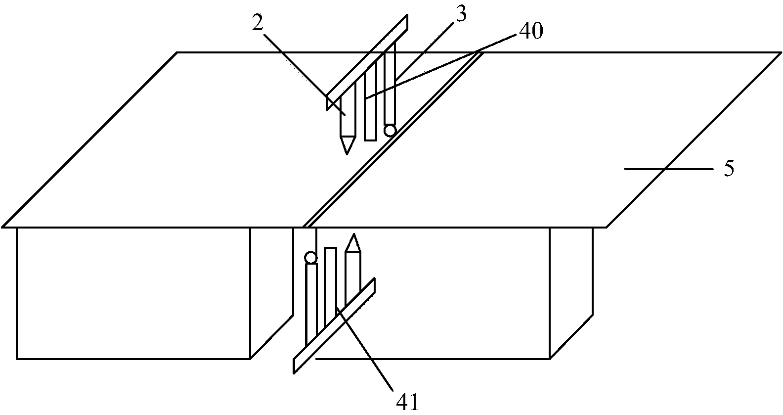
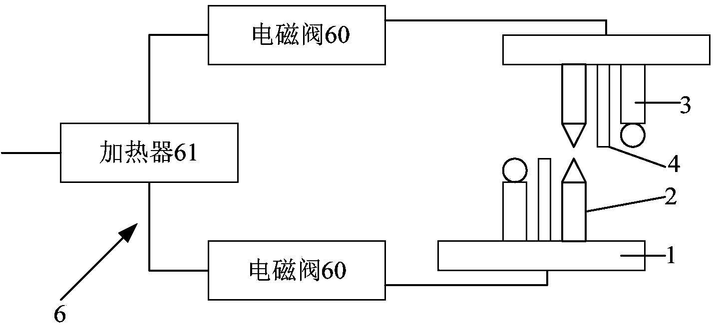
[0020] In order to speed up the cutting efficiency of the glass substrate and improve the cutting quality, the present invention provides a glass substrate cutting equipment, including a worktable 1, a cutting knife 2, a roller 3 and a high-pressure needle nozzle 4, a cutting knife 2, a roller 3 and a high-pressure needle nozzle 4 are arranged in pairs and are symmetrically installed on the upper and lower ends of the glass substrate 5. The glass substrate 5 is transferred on the workbench 1, and the cutting knife 2 includes an upper cutting knife 20 and a lower cutting knife 21, which are respectively arranged on the upper and lower ends of the glass substrate 5 and the knife edges are opposite to each other, so that the upper and lower sides of the glass substrate 5 The glass substrate 5 is cut into two halves. The roller 3 is arranged on the upper end of the glass substrate 5, and the glass substrate 5 can be pressed along the cutting cracks on the glass substrate 5 to break ...


PUM


Abstract

The invention provides glass substrate cutting equipment which comprises a worktable, a cutting knife and a roller, wherein the glass substrate is transferred on the worktable; the cutting knife comprises an upper cutting knife and a lower cutting knife which are respectively arranged at the upper and lower ends of the glass substrate, and the knife edges of the cutting knives are opposite so as to cut the glass substrate into two halves from the upper and lower sides of the glass substrate; the roller is arranged at the upper end of the glass substrate, and the glass substrate can be pressed along the cutting crack on the glass substrate to break the glass substrate. The cutting equipment further comprises a high pressure nozzle mouth which is arranged between the cutting knife and the roller and can eject a high pressure air flow along the cutting crack so as to accelerate breakage of the glass substrate. By additionally arranging the high pressure nozzle mouth which ejects the high pressure air flow to the crack during cutting so as to increase the pressure at the crack and deepen the crack, the effect of quickly cracking is realized.

Description

Technical field [0001] The invention relates to a manufacturing equipment and a preparation method of a glass substrate, in particular to a cutting equipment and a cutting method of a glass substrate. Background technique [0002] The glass substrate of the existing liquid crystal panel needs to be combined with a color filter during the preparation process, and liquid crystal is poured on the substrate, and then cut into the required size. Generally, a cutting knife is used to cut the glass substrate back and forth to cut it into two halves. At this time, due to the long-term use of the cutting knife, the knife head is easy to wear and become blunt. When cutting the glass, the cracks are shallow, making it difficult to break. , It affects the cutting quality of the glass substrate and cannot meet the requirements of refined production of liquid crystal panels. Summary of the invention [0003] Based on the shortcomings of the prior art, the main purpose of the present invention ...

Claims


Application Information

Patent Timeline
Patent Type & Authority Applications(China)
IPC IPC(8): C03B33/02G02F1/13
CPCC03B33/033B26F3/002C03B33/03
Inventor 贾胡平
Owner TCL CHINA STAR OPTOELECTRONICS TECH CO LTD
Why Eureka
Try Eureka