A multifunctional modular shaft

A modular and multi-functional technology, applied in the direction of ball bearings, bearing components, shafts and bearings, etc., can solve the problems of not being able to install electromagnetic brakes, affecting the compactness of size, and complicated design of limit parts, etc. Modular, easy to process effects

Active Publication Date: 2017-02-15
MAQUET SUZHOU
View PDF8 Cites 0 Cited by
  • Summary
  • Abstract
  • Description
  • Claims
  • Application Information

AI Technical Summary

Problems solved by technology

When assembling the large nut of the rotating shaft and connecting the lower flange, special tooling and high-torque electric wrench are required. The processing accuracy of the bearings installed on the inner ring and outer ring of the rotating shaft is relatively high, so the cost of materials and total assembly time is also high. ;The setting of the limit on the outer circumferential surface is not only inconvenient to process, but also affects the compactness of the size; the design of the limit is more complicated and uneconomical; the overall height of the structure is high, and the electromagnetic brake cannot be selected

Method used


Image

  • A multifunctional modular shaft
  • A multifunctional modular shaft
  • A multifunctional modular shaft

Examples


Embodiment 1

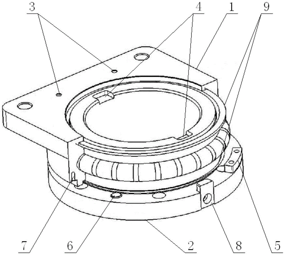
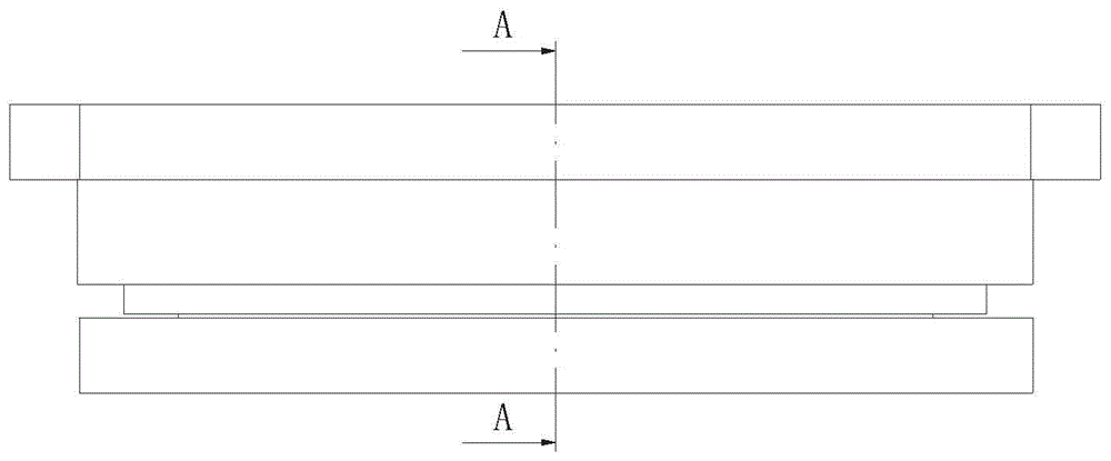
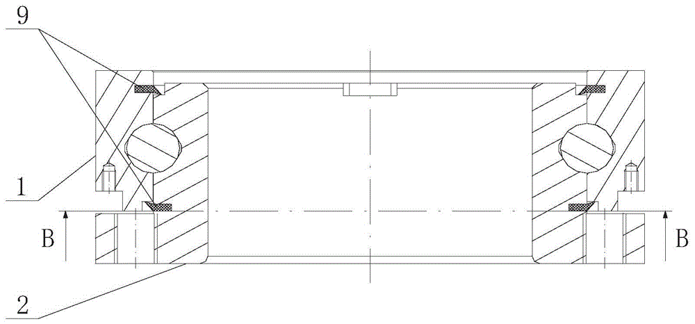
[0020] Such as Figure 1 ~ Figure 4 As shown, a multifunctional modular rotating shaft includes an outer ring of the rotating shaft 1 and an inner ring of the rotating shaft 2, wherein the outer ring of the rotating shaft 1 is an integral forged structure with a flange; the inner ring of the rotating shaft 2 is a An integral forged structure with a flange; the flange top surface of the outer ring of the rotating shaft 1 is provided with four connecting holes 3 for fixing the brake assembly; the bottom surface of the outer ring of the rotating shaft 1 is provided with a number of limit points Degree hole 4, the limit block 5 is installed on the limit index hole 4; the radial inner side of the bottom surface of the outer ring of the rotating shaft 1 is the mechanical braking action surface; the flange of the inner ring of the rotating shaft 2 is on the A number of mechanical brake holes 6 are arranged on the positions corresponding to the mechanical brake action surface; the top...

Embodiment 2

[0022] Such as Figure 5 As shown, an airbag brake is installed above the multifunctional modular rotating shaft.

Embodiment 3

[0024] Such as Image 6 As shown, an electromagnetic brake is installed above the multifunctional modular rotating shaft.


PUM


Abstract

The invention discloses a multifunctional modular rotating shaft, relates to the field of medical crane rotating shafts, and solves the problems that a conventional rotating shaft is complicated in assembling, high in difficulty and long in time, a limiting piece is complicated and non-economic in design, the overall structure is not compact, and an electromagnetic brake cannot be alternatively assembled. The multifunctional modular rotating shaft comprises an outer rotating shaft ring and an inner rotating shaft ring, wherein the outer rotating shaft ring is of an overall forged structure with a flange; the inner rotating shaft ring is of an overall forged structure with a flange; connection holes are formed in the top surface of the flange of the outer rotating shaft ring; limiting indexing holes, limiting blocks and a mechanical braking acting surface are arranged on the outer rotating shaft ring; mechanical braking holes, braking component clamping slots and limiting columns are arranged on the inner rotating shaft ring. By the adoption of an embedding method for arranging the limiting blocks and the limiting columns, the overall structure is compact, the whole size and the weight of the rotating shaft are reduced, the design is modularized, the rotating shaft assembling time is shortened, and an air bag brake and the electromagnetic brake can be alternatively assembled. The multifunctional modular rotating shaft is suitable for the field of medical instruments.

Description

technical field [0001] The invention relates to the field of medical pendant rotating shafts, in particular to a multifunctional modular rotating shaft. Background technique [0002] At present, the product structure of the rotating shaft of the medical pendant is as follows. An independent bearing is installed between the inner ring and the outer ring of the rotating shaft. The lower end of the inner ring of the rotating shaft is connected with a flange through threads, and the upper surface of the flange is fixed with an airbag brake, a mechanical brake and a limiter. There is an indexing threaded hole on the outer circumferential surface of the outer ring of the rotating shaft, which is used to install another part of the limit. When assembling the large nut of the rotating shaft and connecting the lower flange, special tooling and high-torque electric wrench are required. The processing accuracy of the bearings installed on the inner ring and outer ring of the rotating s...

Claims


Application Information

Patent Timeline
Patent Type & Authority Patents(China)
IPC IPC(8): F16C19/06F16C33/58
Inventor 陶晓旺黎群华吉鸣
Owner MAQUET SUZHOU
Why Eureka
Try Eureka