Two-way flow control valve

A flow control valve, two-way acting technology, applied in the direction of valve details, multi-way valves, safety valves, etc., can solve the problems of complex valve system design, flow fluctuation, flow control rules are not easy to change, etc., to achieve a wide range of pressure regulation, flow Effects with continuous control and simple structure

Active Publication Date: 2014-07-02
JILIN UNIV
View PDF9 Cites 3 Cited by
  • Summary
  • Abstract
  • Description
  • Claims
  • Application Information

AI Technical Summary

Problems solved by technology

The disadvantage is that the design of the valve system is complex, the flow control rules are not easy to

Method used


Image

  • Two-way flow control valve
  • Two-way flow control valve
  • Two-way flow control valve

Examples


Example Embodiment

[0040] The present invention will be described in detail below in conjunction with the drawings.

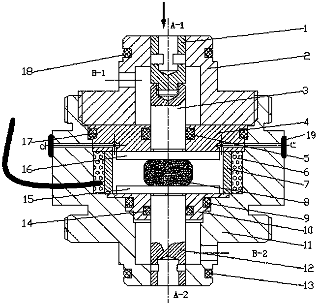
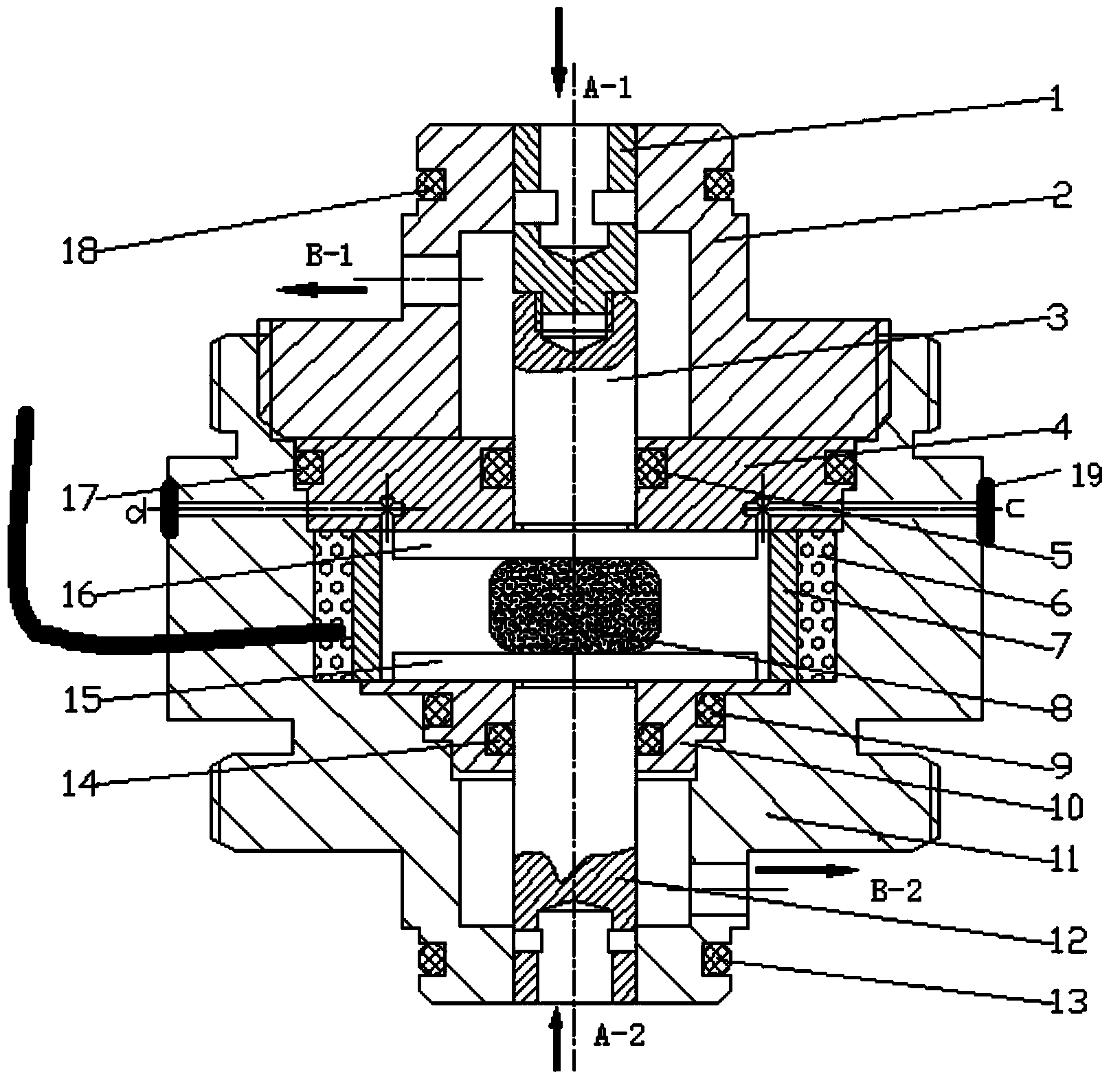
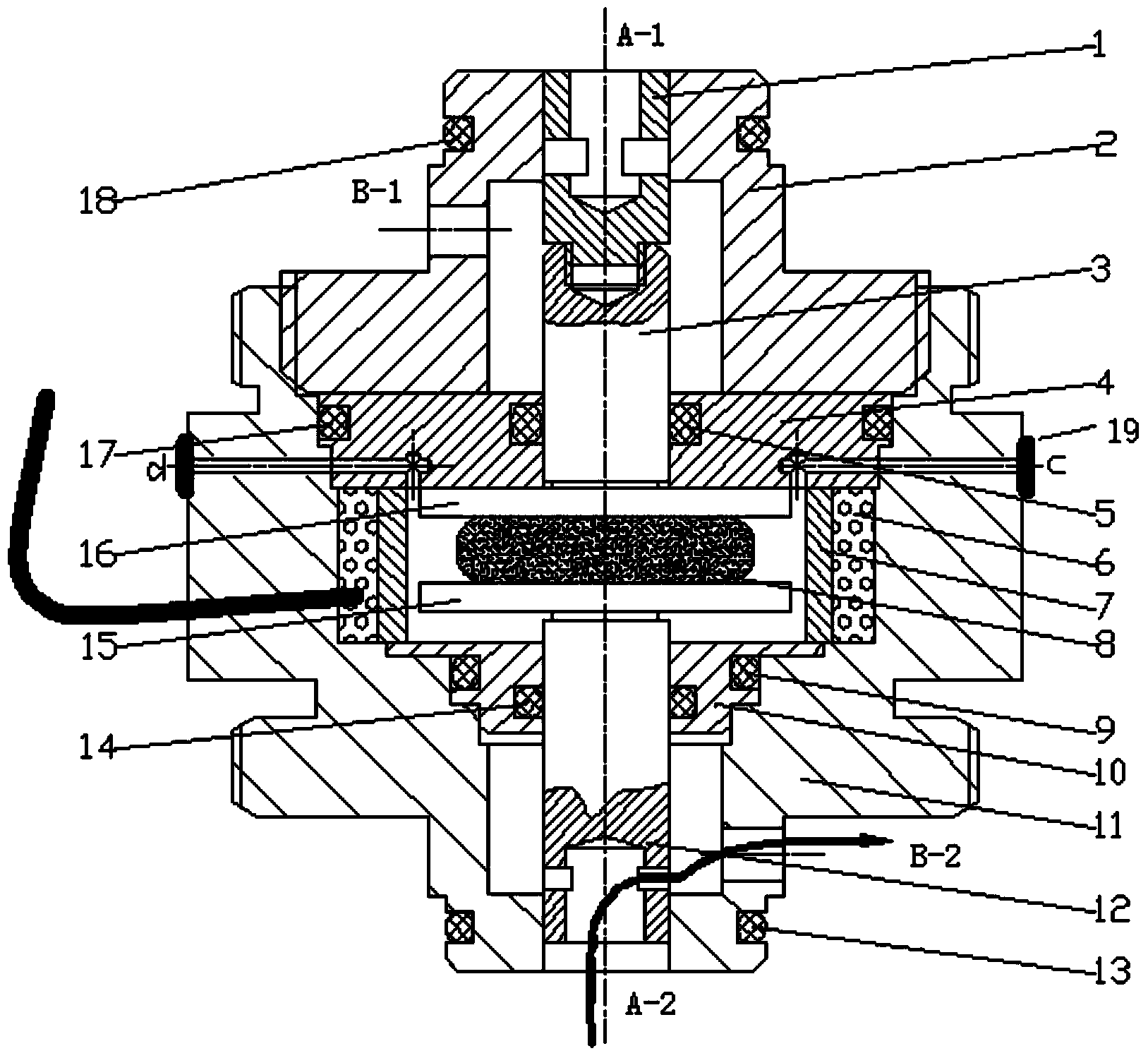
[0041] Such as figure 1 As shown, a two-way acting flow control valve of the present invention includes an upper valve body 2 and a lower valve body 11 that are coaxially fixedly connected, wherein the upper valve body 2 is coaxially installed with an upper valve core 1 from top to bottom. , The upper thrust rod 3 and the upper inner valve body 4; the inside of the lower valve body 11 is coaxially installed with a lower thrust rod 12 and a lower inner valve body 10 from bottom to top, as well as nested coils 6 and magnetic isolation sleeves 7 ;

[0042] Inside the magnetic isolation sleeve 7, between the upper thrust rod 3 and the lower thrust rod 12, an upper pole plate 16, a magnetorheological elastic body 8 and a lower pole plate 15 are sequentially installed from top to bottom.

[0043] Among them, the lower part of the upper thrust rod 3 and the upper pole plate 16, the upper pa...


PUM


Abstract

The invention discloses a two-way flow control valve. The two-way flow control valve comprises an upper valve body 2 and a lower valve body 11 which are coaxially and fixedly connected with each other. An upper valve core 1, an upper thrust bar 3 and an upper inner valve body 4 are sequentially installed in the upper valve body 2 from top to bottom. A lower thrust bar 12, a lower inner valve body 10, a coil 6 and a non-magnetic sleeve 7 are sequentially and coaxially installed in the lower valve body 11 from bottom top, and the coil 6 and the non-magnetic sleeve 7 are arranged in a nested mode. An upper pole plate 16, a magnetorheological elastomer 8 and a lower pole plate 15 are sequentially installed in the non-magnetic sleeve 7 and located between the upper thrust bar 3 and the lower thrust bar 12 from top to bottom. The two-way flow control valve is further provided with two oil inlet and oil outlet sets. By means of the two-way flow control valve, continuous control over flow and control over valve opening pressure can be achieved by controlling magnetic field intensity, and the valve opening pressure can be changed according to external use conditions; besides, two-way pressure control is achieved through one coil, and therefore the two-way flow control valve can serve as two one-way flow control valves; the two-way flow control valve is high in response speed and wide in pressure control range.

Description

Technical field [0001] The invention relates to a two-way flow control valve, which can realize continuous flow control and valve opening pressure control by controlling the intensity of a magnetic field, and a set of coils are shared to realize pressure control in two directions of action. It can also be used as two one-way flow control valves. Background technique [0002] Dampers are widely used in vibration reduction systems. The valve system of the damper is the key to its design. The traditional mechanical valve system realizes flow control through the superposition of valve plates. The disadvantage is that the valve system design is complicated, the flow control rules are not easy to change after the design is completed, and the flow fluctuates when the corresponding valve plate is opened. With the development of science and technology, the dampers are developing in the direction of intelligence and precision, which requires us to design more precise valve systems to achi...

Claims


Application Information

Patent Timeline
IPC IPC(8): F16K17/20F16K31/06
CPCF16F9/34F16K11/161F16K31/0613
Inventor 章新杰石冰张玉新郭孔辉李若琳刘雅丹杨悦
Owner JILIN UNIV
Why Eureka
Try Eureka