Light guiding plate and backlight module

A technology for a backlight module and a light guide plate, applied in the field of optical components, can solve the problems of uneven surface light source, increased cost, reduced service life of light-emitting diodes, etc., and achieves the effects of improving luminance uniformity, reducing hot spots, and increasing luminance.

Inactive Publication Date: 2014-07-02
YOUNG LIGHTING TECHNOLOGY INC
View PDF9 Cites 6 Cited by
  • Summary
  • Abstract
  • Description
  • Claims
  • Application Information

AI Technical Summary

Problems solved by technology

These bright and dark areas will lead to uneven surface light source provided by the light guide plate, which is the so-called hot spot phenomenon.
Therefore, the dark and bright areas produced by the hot spot phenomenon will reduce the overall uniformity of the surface light source provided by the backlight module, and make it difficult to improve the overall optical quality of the liquid crystal display.
Although the hot spot phenomenon can be reduced by increasing the number of LEDs, however, increasing the number of LEDs will not only increase the cost, but also increase the overall temperature and reduce the service life of the LEDs

Method used


Image

  • Light guiding plate and backlight module
  • Light guiding plate and backlight module
  • Light guiding plate and backlight module

Examples


Embodiment Construction

[0076] The aforementioned and other technical content, features and effects of the present invention will be clearly presented in the following detailed description of preferred embodiments with accompanying drawings. The directional terms mentioned in the following embodiments, such as: up, down, left, right, front or back, etc., are only referring to the directions of the drawings. Accordingly, the directional terms are used to illustrate and not to limit the invention.

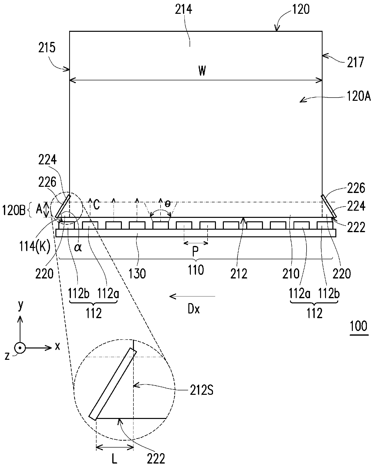
[0077] Figure 1A It is a schematic top view of the backlight module 100 according to an embodiment of the present invention. Figure 1A' for Figure 1A Partially enlarged front view schematic diagram of . Please refer to Figure 1A and Figure 1A' , the backlight module 100 of this embodiment includes a light source device 110 and a light guide plate 120 .

[0078] The light source device 110 includes a plurality of point light sources 112 arranged along an extending direction Dx. Each point light sour...


PUM


Abstract

The invention discloses a light guiding plate and a backlight module. The backlight module comprises a light source device and a light guiding plate. The light source device comprises a plurality of point light sources arranged along an extension direction, and the point light sources can be respectively used to provide a light beam. The light guiding plate comprises a rectangular main body and two triangular protruding parts. The main body is provided with a first light-incoming surface, a light-outgoing surface, and a bottom surface with respect to the light-outgoing surface. The first light-incoming surface is adjacent to the bottom surface and the light-outgoing surface, and the first light-incoming surface is in the shape of a rectangle, and is extended along the extension direction. The protruding parts are respectively protruded from one of the two short edges of the first light-incoming surface toward the extension direction. Each of the protruding parts is respectively provided with a second light-incoming surface and a reflective side surface, and the second light-incoming surface is adjacent to the first light-incoming surface, and is parallel to the first light-incoming surface. The light guiding plate and the backlight module can be used to provide the surface light source with high uniformity.

Description

technical field [0001] The present invention relates to an optical component, and in particular to a light guide plate and a backlight module thereof. Background technique [0002] With the progress of the display technology, the flat panel display has become the mainstream of the display and has replaced the position of the traditional cathode ray tube (CRT). Among the flat panel displays, a liquid crystal display (LCD) is most widely used by consumers. A general liquid crystal display is mainly composed of a backlight module and a liquid crystal panel. Since the liquid crystal panel itself does not emit light, a backlight module is required to provide a surface light source required for display. [0003] Generally speaking, the known backlight modules can be divided into direct-lit backlight modules and side-lit backlight modules. Taking the side-illuminated backlight module as an example, a light guide plate is generally used to guide the light emitted by a light-emitt...

Claims


Application Information

Patent Timeline
Patent Type & Authority Applications(China)
IPC IPC(8): F21V8/00F21S8/00
Inventor 李建辉李清祥
Owner YOUNG LIGHTING TECHNOLOGY INC
Why Eureka
Try Eureka