Mounting device for ignition needle

An installation device and ignition needle technology, which is applied in household heating, lighting and heating equipment, heating fuel, etc., can solve the inconvenience of replacing spare parts, the trouble of replacing the ignition needle and the position of the ignition needle, and the inability to take out the ignition needle stove accessories, etc. problem, to achieve the effect of convenient use and simple structure

Active Publication Date: 2014-07-02
VATTI CORP LTD
5 Cites 3 Cited by

AI-Extracted Technical Summary

Problems solved by technology

[0002] At present, most of the ignition pins of the existing cookers on the market are fixed by screws. If the ignition pin is not removed, the cooker accessories (such as the fire distributor, etc.) under the ignition pin cannot be taken out.
Such a structural mode brings great inconvenience to cleaning the ...

Method used

A kind of installation device of firing pin, comprises the support 2 that passes the middle part through hole 101 of fire distributor 1, described support 2 is provided with upper boss 201, and described upper boss 201 is provided with through The upper through hole 202, the upper through hole 202 is provided with a lifting rotating rod 3 that can be lifted and rotated in it, and the lifting rotating rod 3 is connected with a gas channel that extends to the fire distributor 1 The ignition pin 4 above 102, the ignition pin 4 is completely in the middle through hole 101 after the lifting rotation rod 3 is lifted and rotated, and the lower part of the lifting rotation rod 3 is provided with a blocking device 5, A spring 6 sleeved on the lifting rotating rod 3 is provided between the blocking device 5 and the upper boss 201, and a spring 6 is set between the support 2 and the lifting rotating rod 3. There is a positioning device 7 for vertically positioning the lifting rotating rod 3 . The ignition pin 4 is connected to the lifting rotary rod 3, and the ignition pin 4 extends above the gas channel 102 on the fire distributor 1. When the fire distributor 1 needs to be taken out, it is only necessary to lift the lifting rotary rod 3 upwards and then rotate the lifting rotary rod 3. The end of ignition needle 4 can no longer interfere with fire distributor 1 when rotating after lift rotating rod 3 is promoted, and ignition needle 4 is just completely in the middle part through hole 101 of distributor 1, and now just can distribute fire 1 is lifted upwards to take out the fire distributor 1, which is very convenient and quick.
Described positioning device 7 comprises the positioning boss 71 that is located at the top of described elevating and rotating rod 3, and described upper boss 201 is provided with for described positioning boss 71 snapping into it when positioning. The card slot 72 inside. The positioning boss 71 snaps into the slot 72, which can prevent the lifting and rotating rod 3 from falling...

Abstract

The invention discloses a mounting device for an ignition needle. The mounting device comprises a bracket penetrating through a middle through hole of a fire distributor, wherein the bracket is provided with an upper lug boss; the upper lug boss has a through upper through hole; the upper through hole is internally provided with a hoisting rotary rod which is hoisted and rotated in the upper through hole; the hoisting rotary rod is connected with the ignition needle stretching above a fuel gas channel on the fire distributor; the ignition needle is completely located in the middle through hole after the hoisting rotary rod is hoisted and rotated; a stopping device is arranged at the lower part of the hoisting rotary rod; a spring sleeving the hoisting rotary rod is arranged between the stopping device and the upper lug boss; a positioning device for positioning the hoisting rotary rod in the vertical direction is further arranged between the bracket and the hoisting rotary rod. The mounting device for the ignition needle is simple in structure; the fire distributor below the ignition needle can be very conveniently taken out so that a user can use conveniently.

Application Domain

Domestic stoves or rangesLighting and heating apparatus +1

Technology Topic

Stops deviceEngineering +1

Image

  • Mounting device for ignition needle
  • Mounting device for ignition needle
  • Mounting device for ignition needle

Examples

  • Experimental program(1)

Example Embodiment

[0027] The present invention will be further described below in conjunction with the drawings:
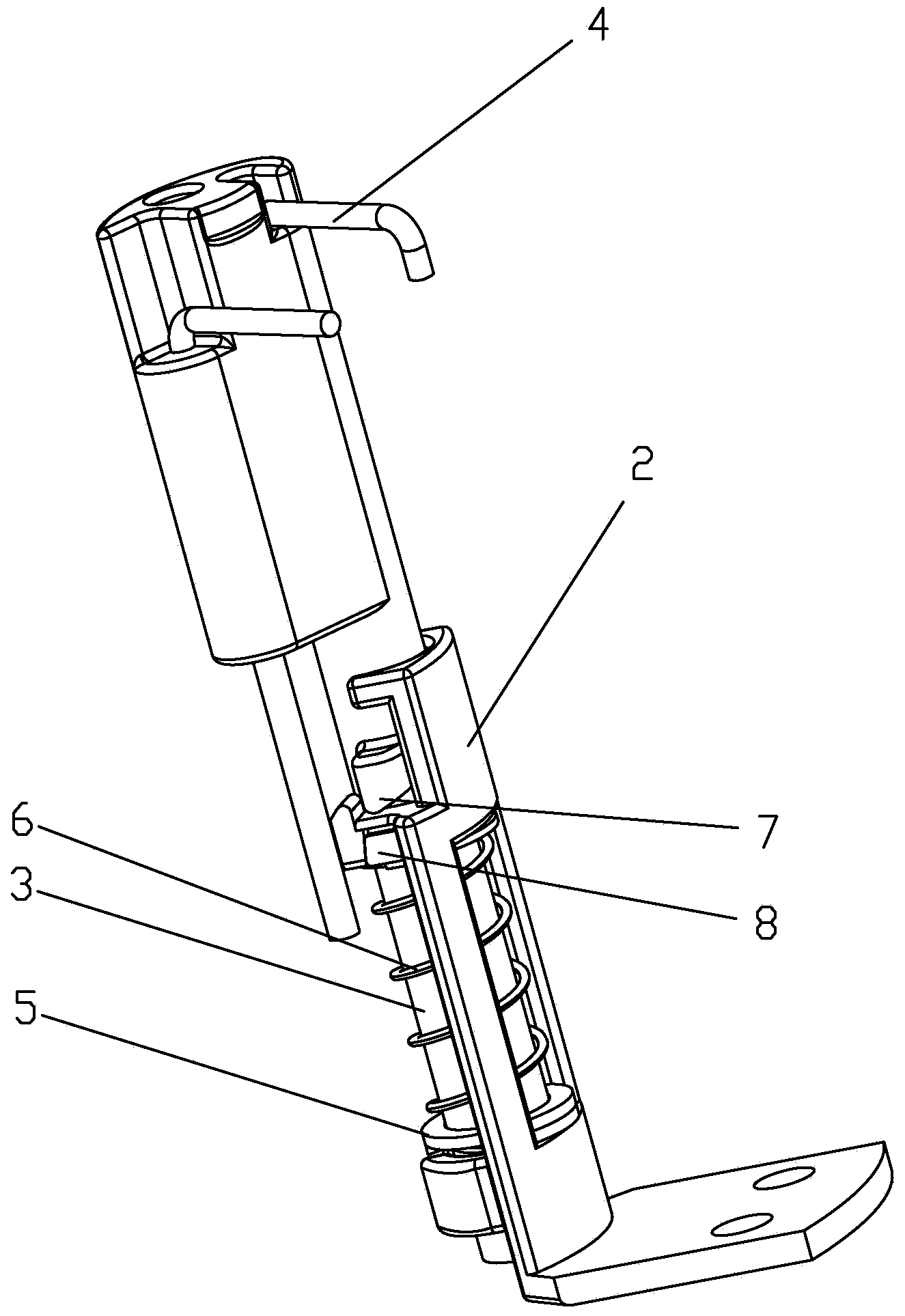
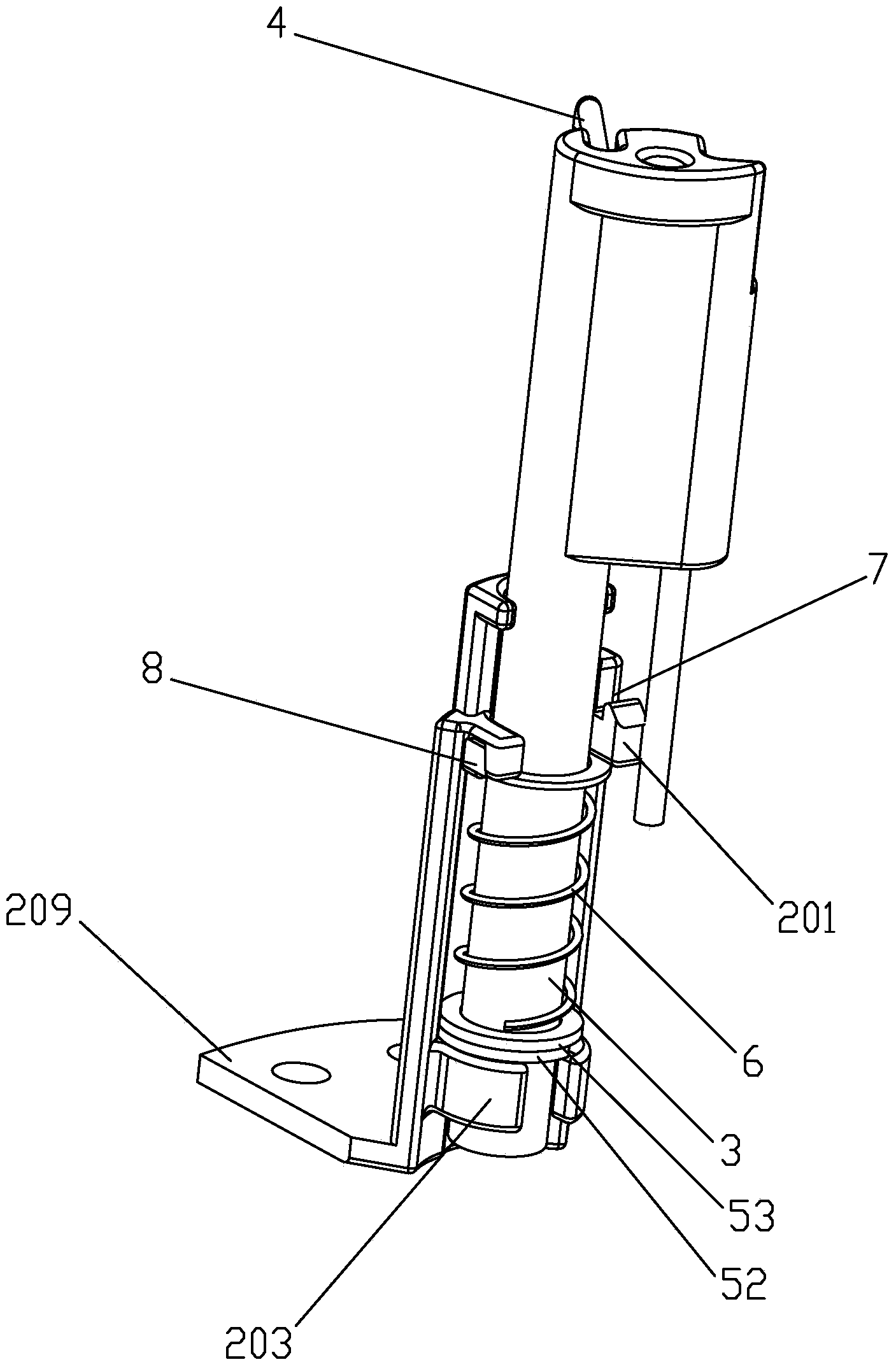
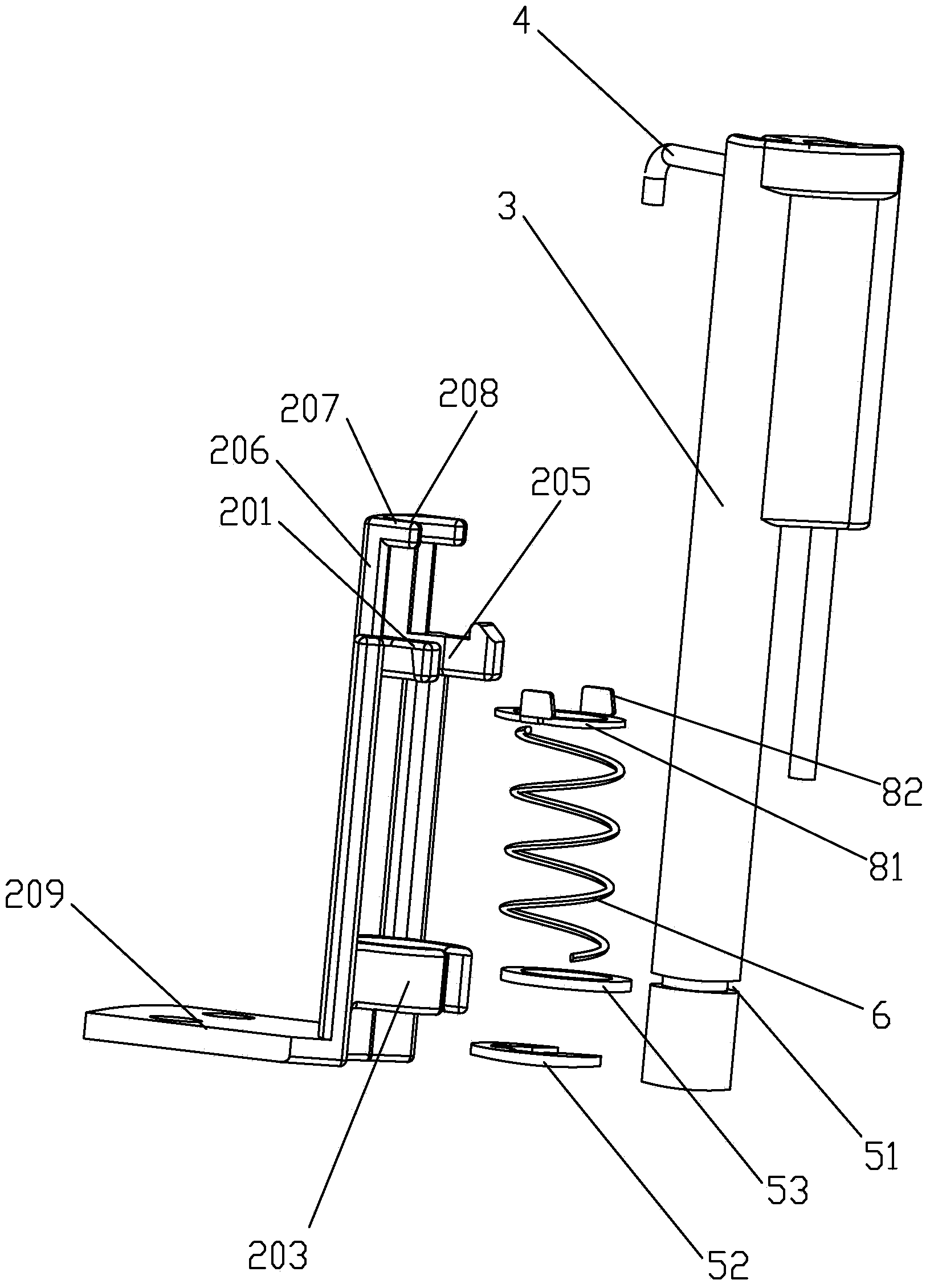
[0028] An installation device for an ignition needle, comprising a bracket 2 passing through the middle through hole 101 of the fire splitter 1, the bracket 2 is provided with an upper boss 201, and the upper boss 201 is provided with a penetrating upper through hole 202. The upper through hole 202 is provided with a lifting and rotating rod 3 that can be raised and lowered and rotated therein, and the lifting and rotating rod 3 is connected with a gas channel 102 that extends above the gas passage 102 on the fire splitter 1 The ignition needle 4, the ignition needle 4 is completely in the middle through hole 101 after the lifting and rotating rod 3 rises and rotates, the lower part of the lifting and rotating rod 3 is provided with a blocking device 5, the Between the blocking device 5 and the upper boss 201 is provided with a spring 6 sleeved on the lifting and rotating rod 3, and between the support 2 and the lifting and rotating rod 3 is also provided with a The positioning device 7 for positioning the lifting and rotating rod 3 in the vertical direction. The ignition needle 4 is connected to the lifting rotating rod 3, and the ignition needle 4 extends above the gas passage 102 on the fire splitter 1. When the fire splitter 1 needs to be taken out, only the lifting rotating rod 3 needs to be lifted up and then the lifting rotating rod 3 is rotated. The end of the ignition needle 4 can no longer interfere with the fire splitter 1 when the lifting rotating rod 3 is lifted, and the ignition needle 4 is completely in the middle through hole 101 of the fire splitter 1, at this time the fire splitter can be 1 Lift up to take out the fire distributor 1, which is very convenient and quick.
[0029] The positioning device 7 includes a positioning boss 71 arranged on the upper part of the lifting and rotating rod 3, and the upper boss 201 is provided with a card for the positioning boss 71 to be clamped into it during positioning. 槽72. The positioning boss 71 is clamped into the slot 72, which can prevent the lifting and rotating rod 3 from falling down in the vertical direction, and also enables the user to locate and prevent the lifting and rotating rod 3 from rotating when it does not need to rotate.
[0030] The blocking device 5 includes an annular groove 51 provided at the lower part of the lifting and rotating rod 3, and a blocking piece 52 for blocking the spring 6 is provided in the annular groove 51.
[0031] The blocking device 5 further includes a lower blocking ring 53 arranged between the blocking piece 52 and the spring 6 and sleeved on the lifting and rotating rod 3 for blocking the spring 6. At this time, the baffle 52 can adopt a circlip, which is a standard part, which is convenient to purchase and low in cost.
[0032] The lower part of the bracket 2 is provided with a lower boss 203, and the lower boss 203 is provided with a lower through hole 204 for the lifting and rotating rod 3 to lift and rotate therein. When the lifting and rotating rod 3 is not lifted, its lower end extends into the lower through hole 204, which can prevent the lifting and rotating rod 2 from tilting and ensure stability.
[0033] The side wall of the upper through hole 202 is provided with a notch 205 for the lifting and rotating rod 3 to be inserted into or taken out of it. The side wall of the upper through hole 202 is provided with a notch 205 for the lifting and rotating rod 3 to be inserted into or taken out of it. When the ignition needle 4 needs to be disassembled and assembled, it only needs to be taken out from the notch 205 together with the lifting and rotating rod 3 or In this way, the quick disassembly and assembly of the ignition needle 4 can be completed, which is very convenient.
[0034] A locking device 8 is provided between the lifting and rotating rod 3 and the bracket 2 to prevent the lifting and rotating rod 3 from falling out of the notch 205. The locking device 8 can prevent the lifting and rotating rod 3 from tilting from the notch 205, thereby preventing the lifting and rotating rod 3 from falling out and the ignition needle 4 from falling down.
[0035] The locking device 8 includes an upper baffle ring 81 arranged between the upper boss 201 and the spring 6 and sleeved on the lifting and rotating rod 3, and the upper baffle ring 81 is A locking piece 82 bent upward is provided, and the upper boss 201 is provided with a locking groove 83 into which the locking piece 82 is locked. The locking piece 82 on the upper baffle ring 81 is locked into the locking groove 83, and the upper baffle ring 81 is sleeved on the lifting and rotating rod 3, thereby preventing the lifting and rotating rod 3 from tilting, and also preventing the lifting and rotating rod 3 from getting out of the gap 205 Prolapse. When the ignition needle 4 needs to be taken out at this time, only the lower end of the lifting and rotating rod 3 needs to be withdrawn from the lower through hole 204, and then the upper stop ring 81 is pressed down to make the locking piece 82 withdraw from the locking groove 83. Take the lifting and rotating rod 3 out of the notch 205, and the ignition needle 4 connected to the lifting and rotating rod 3 is also taken out immediately.
[0036] The upper boss 201 is provided with an upwardly extending extension rod 206, the extension rod 206 is provided with a boss 207, and the boss 207 is provided with an opening and capable of rotating the lifting A guide groove 208 for guiding the rod 3 when it is raised and lowered.
[0037] The bracket 2 is provided with a mounting plate 209 for fixing it to the furnace body 9.

PUM

no PUM

Description & Claims & Application Information

We can also present the details of the Description, Claims and Application information to help users get a comprehensive understanding of the technical details of the patent, such as background art, summary of invention, brief description of drawings, description of embodiments, and other original content. On the other hand, users can also determine the specific scope of protection of the technology through the list of claims; as well as understand the changes in the life cycle of the technology with the presentation of the patent timeline. Login to view more.

Similar technology patents

Photoelectric sensor for position of sun

InactiveCN101650173AEffective tracking range expandedSimple structure
Owner:WUHAN UNIV OF TECH

Magnetic cooling apparatus and control method thereof

ActiveUS20130180263A1simple structure
Owner:SAMSUNG ELECTRONICS CO LTD

Dual-Drivetrain of Power-Assist Vehicle

InactiveUS20100181130A1enhance uphill momentumsimple structure
Owner:CHOU WEN CHENG

Classification and recommendation of technical efficacy words

  • Simple structure
  • easy to use

Laser assisted total joint arthroplasty

InactiveUS20090234360A1easy to use
Owner:ALEXANDER VLADIMIR

Enclosure for a portable hemodialysis system

ActiveUS20090114582A1easy to use
Owner:DEKA PROD LLP
Why Eureka
Try Eureka