Supercharge Your Innovation With Domain-Expert AI Agents!

a freeze dryer

一种冻干机、冻干的技术,应用在冻干机领域,能够解决组装运输不方便、制造组装困难、制造成本高等问题,达到避免污染风险、节省制造材料、结构紧凑的效果

Active Publication Date: 2016-03-23
TRUKING TECH LTD
View PDF7 Cites 0 Cited by
  • Summary
  • Abstract
  • Description
  • Claims
  • Application Information

AI Technical Summary

Problems solved by technology

This kind of freeze dryer has the following disadvantages: 1. The freeze-drying box and the cold trap are connected through a connecting pipe, and the connecting pipe needs to open a large hole on the freeze-drying box and the cold trap, and install it with a large flange. The valve leads to complex structure, high cost, and difficult manufacturing and assembly. The driving cylinder of the on-off valve will also cause pollution to the product; 2. The freeze-drying box and the cold trap are two independent containers arranged horizontally side by side, and the manufacturing cost is high. , Take up a lot of space, and it is inconvenient to assemble and transport

Method used


Image

  • a freeze dryer
  • a freeze dryer
  • a freeze dryer

Examples


Embodiment 1

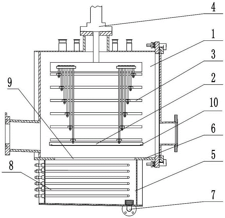
[0029] Such as figure 1 As shown, the lyophilizer of the present invention includes a freeze-drying chamber 1 and a cold trap chamber 5, and a coil 8 for refrigeration is provided in the cold-trap chamber 5; Above the multiple freeze-dried slabs 3, the top of the freeze-dried chamber 1 is provided with a lifting drive 4 for driving the support plate 2 and the freeze-dried slabs 3 up and down. The lifting drive 4 in this embodiment is an oil cylinder. During work, after the bottle body in a half-stoppered state completes freeze-drying on the freeze-drying plate layer 3, the support plate 2 and each freeze-drying plate layer 3 will move down under the drive of the lifting drive member 4, so that each freeze-drying plate layer The layers 3 are close to each other for plugging, and the rubber stopper on the bottle body is completely pressed into the bottle mouth; the support plate 2 is lowered to the bottom of the freeze-drying chamber 1 to support the freeze-dried plate layer 3 ....

Embodiment 2

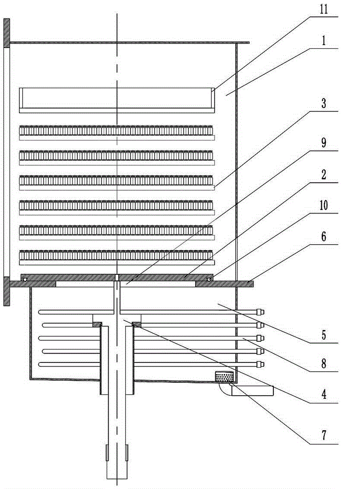
[0035] Such as image 3 and Figure 4 As shown, this embodiment is basically the same as Embodiment 1, the only difference is that in this embodiment, the lifting drive member 4 is arranged at the bottom of the cold trap chamber 5, when the support plate 2 descends to the bottom of the freeze-drying chamber 1 and covers the through When opening the hole 9, the lift driver 4 exerts a downward pulling force on the support plate 2, driving the support plate 2 to be pressed against the periphery of the through hole 9, thereby obtaining a better sealing and isolation effect, and measuring the pressure of the freeze-drying chamber 1 more accurately. liters, to accurately judge whether the freeze-drying is sufficient (the freeze-drying machine mainly evaporates the water in the mixture in the bottle, and the freeze-drying chamber 1 needs to be sealed before plugging, and the pressure rise of the freeze-drying chamber 1 should be measured, if the freeze-drying chamber 1 If the pressu...


PUM


Abstract

A freeze dryer, comprising a freeze-drying chamber (1) and a cold trap chamber (5); the freeze-drying chamber (1) is provided with a support plate (2) and multiple freeze-drying plate layers (3) located above the support plate (2); the support plate (2) is connected to a lift drive component (4) for lifting the support plate (2) and the freeze-drying plate layer (3); the freeze-drying chamber (1) is located above the cold trap chamber (5), and communicates with the cold trap chamber (5) via a through hole (9) arranged at the bottom of the freeze-drying chamber (1); and the cold trap chamber (5) or the freeze-drying chamber (1) is provided with a seal for covering the through hole (9) to separate the freeze-drying chamber (1) from the cold trap chamber (5). The freeze dryer has a simple structure, low cost, small footprint, and low pollution risk.

Description

technical field [0001] The invention mainly relates to the field of food and medicine packaging machinery, in particular to a freeze dryer. Background technique [0002] In the field of food and pharmaceutical packaging machinery, the freeze-drying box and the cold trap of the traditional freeze-dryer generally adopt a split structure and are arranged side by side horizontally, that is, the freeze-drying box and the cold trap are two independent containers. It is connected through a pipe and has an independent on-off valve. This kind of freeze dryer has the following disadvantages: 1. The freeze-drying box and the cold trap are connected through a connecting pipe, and the connecting pipe needs to open a large hole on the freeze-drying box and the cold trap, and install it with a large flange. The valve leads to complex structure, high cost, and difficult manufacturing and assembly. The driving cylinder of the on-off valve will also cause pollution to the product; 2. The fre...

Claims


Application Information

Patent Timeline
Patent Type & Authority Patents(China)
IPC IPC(8): F26B5/06F26B25/06F26B25/02
CPCF26B5/06
Inventor 许海兵翁宽李兴波康峰
Owner TRUKING TECH LTD
Features
  • R&D
  • Intellectual Property
  • Life Sciences
  • Materials
  • Tech Scout
  • Unparalleled Data Quality
  • Higher Quality Content
  • 60% Fewer Hallucinations
Learn More