Magnetic element and iron cores thereof

A technology of magnetic components and iron cores, used in electrical components, magnetic cores/yokes, inductors with magnetic cores, etc. Small tolerance range, improved consistency effect

Inactive Publication Date: 2014-07-02
DELTA ELECTRONICS (SHANGHAI) CO LTD
View PDF6 Cites 1 Cited by
  • Summary
  • Abstract
  • Description
  • Claims
  • Application Information

AI Technical Summary

Problems solved by technology

However, limited by the thickness tolerance of Mylar, the inductance tolerance range of the magnetic components in this way will reach plus or minus 25% or more under normal circumstances, which brings great difficulties to the consistency of power supply products and affects the reliability of the circuit. sex and stability

Method used


Image

  • Magnetic element and iron cores thereof
  • Magnetic element and iron cores thereof
  • Magnetic element and iron cores thereof

Examples


no. 1 example

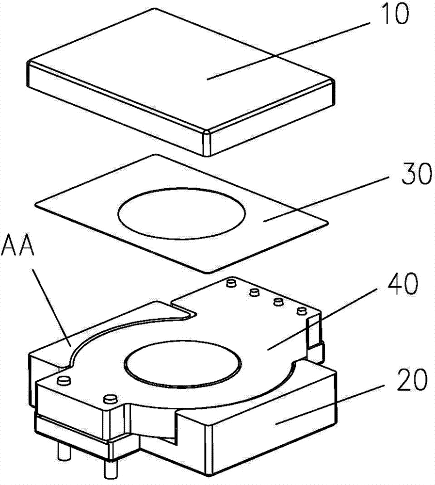
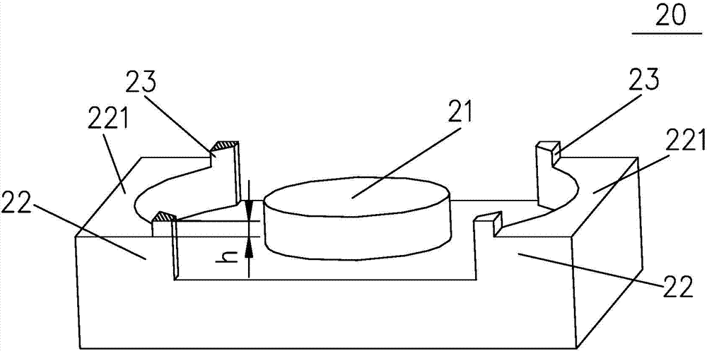
[0050] In order to realize that the air gap can be distributed and set, and effectively reduce the tolerance range of the inductance, the iron core of the first embodiment proposed by the present invention is as follows: Figure 2a with Figure 2b shown. The iron core 20 includes a plurality of joint surfaces 221 and a plurality of protrusions 23 . The joint surface 221 is used for jointing with another iron core; a plurality of bosses 23 are arranged on the joint surface 221 to generate mechanical support for the other iron core, and the bosses 23 have a height dimension, which is used to control the magnetic The air gap size of the component.

[0051] In this embodiment, the EQ iron core is taken as an example. The iron core 20 includes a central column 21 and two side columns 22 , and the two side columns 22 are arranged on the periphery of the central column 21 . The joint surface refers to the surface where the two iron cores are assembled when there is no boss, such a...

no. 2 example

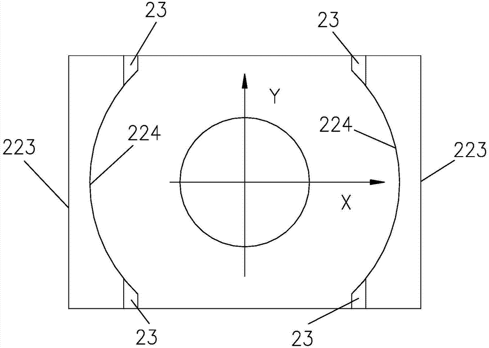
[0060] Such as Figure 3a with 3b Shown is another embodiment of the present invention. The iron core of this embodiment has substantially the same structure as that of the first embodiment, except that the type of the iron core is different. The iron core of this embodiment is an RM iron core, while the iron core of the first embodiment is an EQ iron core. When forming the boss 23, it is only necessary to grind along the X-axis direction, thereby reducing the number of times of grinding.

[0061] In this embodiment, there are two bosses on the left column and the right column of the RM iron core respectively, and the upper surfaces of these four bosses are closely attached to the opposite iron core to form a new combined surface.

[0062] The main difference between the magnetic element of the present invention and the magnetic element of the prior art lies in the structure of the iron core. Specifically, the iron core of the magnetic element of the present invention adopt...


PUM


Abstract

The invention discloses a magnetic element. The magnetic element comprises two opposite iron cores and an electric conduction winding arranged between the two iron cores. An air gap is reserved between the two iron cores. At least one of the two iron cores comprises a plurality of adjoining planes and a plurality of bosses, the adjoining planes are used for being connected with the iron cores opposite to the adjoining planes, and the bosses are arranged on the adjoining planes to mechanically support the iron cores opposite to the bosses. The bosses have a certain height used for controlling the size of the air gap. According to the magnetic element and the iron cores, the bosses are arranged on the adjoining planes of the iron cores, the air gap is dispersed to all magnetic columns of the iron cores, the tolerance range of the inductance value is effectively reduced, and the consistency of the magnetic element is improved.

Description

technical field [0001] The invention relates to a magnetic element, in particular to an iron core of the magnetic element. Background technique [0002] In magnetic components such as inductors and transformers, the air gap is a very important part of the magnetic circuit, and it has a great influence on the inductance value, saturation current, and frequency characteristics of the magnetic component. Therefore, the material, size, position, and bonding strength of the air gap are the objects that need to be controlled in the production of magnetic components. [0003] The iron core of the existing magnetic element with air gap is often made of ferrite material, the material is hard and brittle, and the iron core of EI, EE, EQ, RM, etc. with three magnetic columns (that is, three contact surfaces) is generally used in shape. structure. In order to obtain inductance with a small tolerance, the air gap is usually set in the middle column of the iron core, and the air gap is ...

Claims


Application Information

Patent Timeline
Patent Type & Authority Applications(China)
IPC IPC(8): H01F27/26H01F3/14H01F17/04
CPCH01F3/14H01F27/263H01F27/306
Inventor 卢增艺朱少华夏伟龙章进法
Owner DELTA ELECTRONICS (SHANGHAI) CO LTD
Why Eureka
Try Eureka