Battery pack

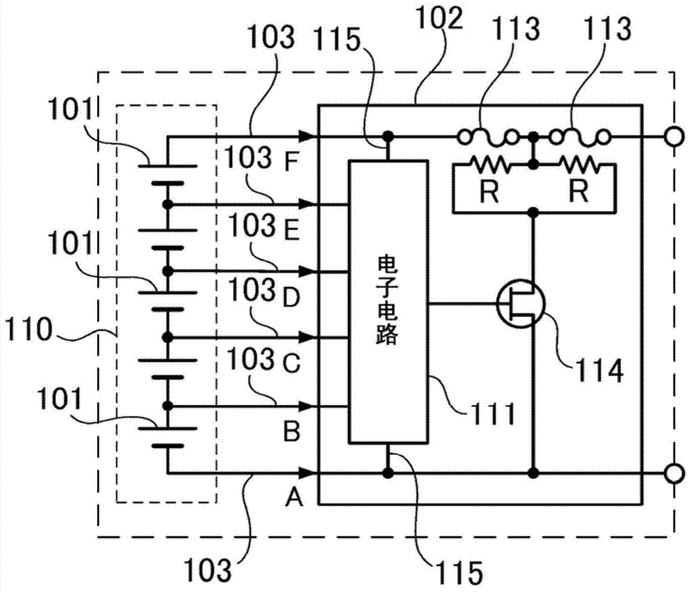
A technology for battery packs and single cells, which is applied to battery pack components, secondary batteries, circuits, etc., can solve problems such as component damage, failure, and inability to correctly detect the voltage of single cells 101, so as to prevent electronic circuit failures. Effect

Active Publication Date: 2014-07-02
PANASONIC ENERGY CO LTD MORIGUCHI SHI
View PDF3 Cites 4 Cited by
  • Summary
  • Abstract
  • Description
  • Claims
  • Application Information

AI Technical Summary

Problems solved by technology

For example, in figure 1 If the lead wires 103 are not connected in the order of A, B, C..., connect the lead wire 103 of E after connecting A of the ground wire and F of the power supply wire 115 on the positive side to make the electronic circuit 111 work. , the electronic circuit 111 cannot correctly detect the voltage of the cell 101, and it is determined that the cell 101 has risen to an abnormal voltage, the switching element 114 is turned on, and the current flows through the heating resistor provided between the fuses 113, 113 and the switching element 114 R, resulting in disadvantages such as fuse 113 blown
In addition, if the lead wire 103 of E is connected before the lead wire 103 of D is connected, the voltage difference between the input terminals becomes very large, and a voltage exceeding the withstand voltage is input to the input side of the electronic circuit 111, causing problems such as failure.
Since the electronic circuit was selected assuming the voltage detection of a single cell, the resistance to the high voltage formed by the series connection of multiple cells was not considered in the design. Risk of component damage due to high voltage

Method used


Image

  • Battery pack
  • Battery pack
  • Battery pack

Examples


Embodiment Construction

[0040] Hereinafter, embodiments of the present invention will be described based on the drawings. However, the embodiments shown below are examples of battery packs for embodying the technical idea of ​​the present invention, and the battery packs of the present invention are not limited to the following battery packs. Furthermore, in this specification, in order to make understanding of a claim easy, the code|symbol corresponding to the member shown in an Example is added to the member shown in "claim" and "means to solve the problem." However, the means shown in the claims are by no means specified as the means of the embodiment.

[0041] Hereinafter, an example applied to a power supply device for an assist bicycle as a battery pack according to an embodiment of the present invention will be described. Figure 4 and Figure 5 The illustrated battery pack is composed of a battery module 10 in which a plurality of cells 1 are connected, a circuit board 2 connected to the ce...


PUM


Abstract

The present invention is provided with the object of having guide wires connected ideally with the connection plate of an electric circuit substrate in a welding order. Therefore, the battery pack of the invention is provided with plural battery electrode terminals that are connected in series and are connected to an electric circuit substrate throguh guide wires. The electric circuit substrate is provided with plural connection plates on an insulation substrate and are connected with the electric circuit. At least one of the connection plates is provided with a first connection plate portion connected with the electric circuit and a severing connection plate structred by a second connection plate portion. The severing connection plate makes the first connection plate portion and the second connection plate portion disposed on the surface of the insulation substrate in an un-connected manner and there is a fiber-welding gap. The electric circuit substrate is provided with a throughhold connecting with the second connection plate portion; when the through hole is inserted to the second connection plate portion throguh a guide wire in a welding manner, the fiber welding materials enable the first connection plate portion and the second connection plate portion to be mutually connected.

Description

technical field [0001] The present invention relates to a battery pack in which a circuit substrate on which an electronic circuit such as a voltage detection circuit is mounted is connected to a plurality of single cells connected in series via lead wires, and particularly relates to a battery pack which is most suitable for power sources of electric bicycles, electric scooters, etc. Battery. Background technique [0002] With the spread of electrical equipment such as electric scooters and electric bicycles that are driven by receiving electric power from a battery pack, higher output of the battery pack is being sought. In such a battery pack, in order to obtain a large output, a plurality of single cells are connected in series to increase the output voltage. In addition, a lithium-ion secondary cell or the like having a large capacity per unit volume is used as the cell. [0003] In a battery pack using a plurality of cells, it is important to manage the cells in orde...

Claims


Application Information

Patent Timeline
Patent Type & Authority Applications(China)
IPC IPC(8): H01M10/48H01M2/20
CPCH01M10/48H01M50/502Y02E60/10
Inventor 川角笃史寺冈大树
Owner PANASONIC ENERGY CO LTD MORIGUCHI SHI
Why Eureka
Try Eureka