Self-startup circuit and method

A self-starting and circuit technology, applied in the electronic field, can solve problems such as inability to start chips, and achieve the effect of high stability and simple structure

Active Publication Date: 2014-07-02
BEIJING AEONMED
View PDF2 Cites 4 Cited by
  • Summary
  • Abstract
  • Description
  • Claims
  • Application Information

AI Technical Summary

Problems solved by technology

[0004] The invention provides a self-starting circuit and method, which solves the problem that the chip cannot be started when the button cannot be used

Method used


Image

  • Self-startup circuit and method
  • Self-startup circuit and method
  • Self-startup circuit and method

Examples


Embodiment 1

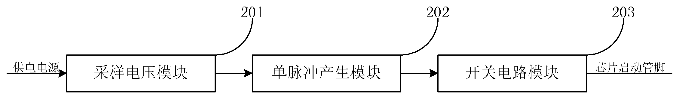
[0038] figure 2 It is a functional module block diagram of a self-starting circuit system provided by Embodiment 1 of the present invention, such as figure 2 Shown:

[0039] A self-starting circuit comprising:

[0040] The sampling voltage module 201 divides the power supply voltage to obtain a sampling voltage; the single pulse generation module 202 is connected with the sampling voltage module 201 and generates a single pulse signal by using the sampling voltage; the switching circuit module 203 is connected with the single pulse generation module 202 , according to the single pulse signal to control the on-off of the start-up circuit, thereby generating the start-up signal.

[0041] Wherein, the sampling voltage module 201 further includes:

[0042] The first voltage-dividing resistor and the second voltage-dividing resistor, the first voltage-dividing resistor and the second voltage-dividing resistor are connected in series, connected between the power supply and the ...

Embodiment 2

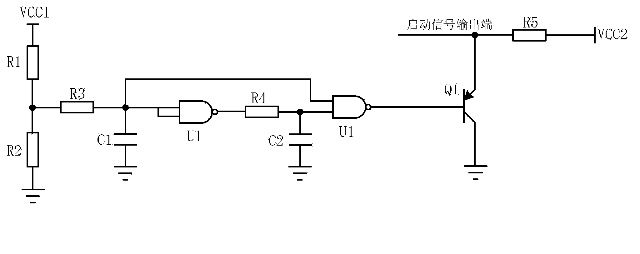
[0052] image 3 It is a schematic diagram of a self-starting circuit preferably provided by Embodiment 2 of the present invention, such as image 3 Shown:

[0053]The first voltage dividing resistor R1 and the second voltage dividing resistor R2 form a sampling voltage module, the first voltage dividing resistor R1 and the second voltage dividing resistor R2 are connected in series, connected between the power supply and the ground, and divide the power supply voltage, To obtain the sampling voltage, by adjusting the resistance of the first voltage dividing resistor R1 and the second voltage dividing resistor R2, different sampling voltages can be obtained to meet the requirements of different sampling voltages. The first voltage dividing resistor R1 and the second voltage dividing resistor R1 The connection point of the resistor R2 is used as the sampling voltage output terminal.

[0054] The first current-limiting resistor R3, the first capacitor C1, the first logic gate U...

Embodiment 3

[0067] Figure 5 It is a schematic diagram of a self-starting circuit preferably provided by Embodiment 3 of the present invention, as shown in Figure 5 Shown:

[0068] The difference between this embodiment and Embodiment 2 is that this embodiment preferably adopts the following connection mode: connect the first delayed voltage output terminal to one input terminal of the first logic gate U1, and the other input terminal of the first logic gate U1 One input terminal is connected to the sampling voltage output terminal, the two input terminals of the NAND gate U2 are respectively connected to the first delayed voltage output terminal and the second delayed voltage output terminal, and the output terminal of the NAND gate U2 outputs a single pulse Signal.

[0069] Other devices and connection methods of this embodiment are the same as those of Embodiment 2, and the same parts will not be repeated here.

[0070] The basic principle of the circuit connected by this connectio...


PUM


Abstract

The invention provides a self-startup circuit and method. The self-startup circuit comprises a sampling voltage module which is used for performing voltage division on power supply voltages and obtaining sampling voltages, a monopulse generation module which is connected with the sampling voltage module and utilizes the sampling voltages to generate monopulse signals, and a switch circuit module which is connected with the monopulse generation module and controls the on-off of the startup circuit according to the monopluse signals so as to generate startup signals. According to the technical scheme provided by the invention, through performing two-stage time delay on the sampling voltages and logic calculation on voltages after time delay for two times, the monopulse signals are obtained, and by use of the monopulse signals, the startup circuit is controlled, and the startup signals capable of starting a chip are generated, so that the problem of incapability of starting a chip when a button cannot be used, the chip can be automatically started, manual control is unnecessary, the equipment structure is simpler, and the starting stability is higher.

Description

technical field [0001] The invention relates to the field of electronic technology, in particular to a self-starting circuit and method. Background technique [0002] With the continuous development of computer technology, devices using chips such as various processors CPU, single-chip microcomputer, DSP, FPGA and ARM appear in every corner of society and life. Because these devices have various advantages such as small size, high performance, portability, and strong pertinence, these devices have been widely used in various fields of society. Before running the above-mentioned chips, it is necessary to send a start signal to the start pin of the chip. In the past, the chip was usually started by pressing a button. figure 1 It is a key-type starting circuit in the prior art. Such as figure 1 As shown: Among them, the connection point of the resistor R39 and the key switch SW2 is the start signal output terminal, which is connected to the start pin of the chip, and the chi...

Claims


Application Information

Patent Timeline
Patent Type & Authority Applications(China)
IPC IPC(8): H03K17/60
Inventor 祁业鹏
Owner BEIJING AEONMED
Why Eureka
Try Eureka