Brushless harmonic excitation motor with initial self-starting capacity

A brushless harmonic and self-starting technology, applied in the direction of electrical components, electromechanical devices, synchronous machine parts, etc., can solve the problems of difficult to achieve weak magnetic speed expansion, difficult to adjust, etc., and achieve simple structure, good performance, and convenient manufacture Effect

Inactive Publication Date: 2014-07-02
HARBIN INST OF TECH
View PDF4 Cites 4 Cited by
  • Summary
  • Abstract
  • Description
  • Claims
  • Application Information

AI Technical Summary

Problems solved by technology

[0005] The present invention aims to solve the problems that the existing permanent magnet generators rely on expensive permanent magnet materials, the air gap magnetic field is difficult to adjust, which makes it difficult to realize the weak field speed expansion, and the existing electric excitation generators need independent exciters

Method used


Image

  • Brushless harmonic excitation motor with initial self-starting capacity
  • Brushless harmonic excitation motor with initial self-starting capacity
  • Brushless harmonic excitation motor with initial self-starting capacity

Examples


specific Embodiment approach 1

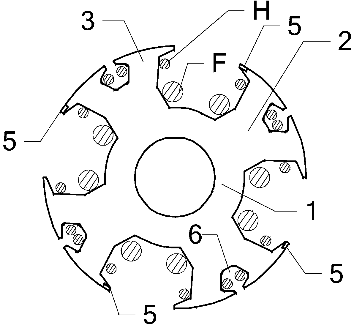
[0022] Specific implementation mode one: see figure 1 Describe this embodiment, a brushless harmonic excitation motor with initial self-starting capability described in this embodiment, the rotor core 1 of the motor has a 4-pole structure, each pole has a rotor main tooth,

[0023] Each rotor main tooth is covered with an excitation winding F, and one end of the pole shoe 2 of each rotor main tooth is provided with a permanent magnet 5 of NdFeB material, and one end of the pole shoe 2 of each rotor main tooth is adjacent to it The other ends of the pole pieces 2 of the rotor main teeth are oppositely arranged, and the excitation directions of the permanent magnets 5 of NdFeB material on the two adjacent rotor main teeth are opposite,

[0024] The middle position of the pole piece 2 of each main tooth of each rotor is provided with a winding slot 6, and the four winding slots 6 divide the four pole pieces 2 into eight rotor teeth 3, and each rotor tooth 3 is nested with a harmo...

specific Embodiment approach 2

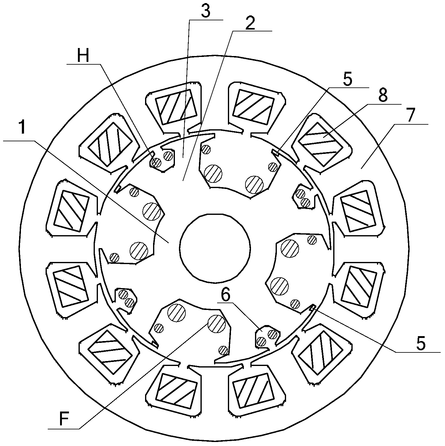
[0028] Specific implementation mode two: see figure 1 and figure 2 Describe this embodiment. The difference between this embodiment and the brushless harmonic excitation motor with initial self-starting capability described in Embodiment 1 is that the stator core 7 of the motor has a 12-slot structure, and the stator is three-phase The winding 8 has a single-layer structure and is an open winding with a pitch of 3.

specific Embodiment approach 3

[0029] Embodiment 3: The difference between this embodiment and the brushless harmonic excitation motor with initial self-starting capability described in Embodiment 1 is that the stator core 7 of the motor has a 12-slot structure, and the stator is three-phase The winding 8 has a double-layer structure and is an open winding with a pitch of 3.


PUM


Abstract

The invention provides a brushless harmonic excitation motor with initial self-starting capacity, and belongs to the field of electrically excited synchronous motors. The brushless harmonic excitation motor solves the problems that an existing permanent magnet generator needs to depend on expensive permanent magnet materials, flux-weakening speed expansion is difficult to achieve due to the fact that the air-gap magnetic field of the existing permanent magnet generator is difficult to adjust, and an existing electrically excited generator needs a separate exciter. A rotor core of the motor is of a four-pole structure, each pole serves as a rotor main tooth, each rotor main tooth is sleeved with an exciting winding, one end of a pole shoe of each rotor main tooth is provided with a permanent magnet made of neodymium iron boron materials, one end of the pole shoe of each rotor main tooth and the other end of the pole shoe of the adjacent rotor main tooth are arranged oppositely, the excitation directions of the permanent magnets made of the neodymium iron boron materials on every two adjacent rotor main teeth are opposite, a winding groove is formed in the middle of the pole shoe of each rotor main tooth, the four winding grooves divide the four pole shoes into eight rotor branch teeth, and harmonic windings are nested in all the rotor branch teeth. The brushless harmonic excitation motor is mainly suitable for hybrid electric vehicles.

Description

technical field [0001] The invention belongs to the field of electric excitation synchronous motors. Background technique [0002] Permanent magnet synchronous motors have gradually been widely used in the industry due to their characteristics of high efficiency and energy saving, high power density and brushless control. Especially in some small and medium power applications, such as the field of electric vehicles. However, these advantages of permanent magnet motors are all based on high-performance rare earth permanent magnet materials. With the development of industry and society, the demand for rare earth resources will continue to increase. In the past ten years, the price of rare earth permanent magnet materials has increased several times, which will make rare earth resources gradually become a bottleneck affecting the development of high-performance permanent magnet motors. Moreover, there are still some technical problems in the permanent magnet synchronous moto...

Claims


Application Information

Patent Timeline
IPC IPC(8): H02K29/00H02K21/02H02K3/16
Inventor 孙立志安群涛姚飞高小龙
Owner HARBIN INST OF TECH
Why Eureka
Try Eureka