Check patentability & draft patents in minutes with Patsnap Eureka AI!

Display data channel switching device and display data channel switching method

A technology for displaying data channels and switching devices, applied in image communication, static indicators, cathode ray tube indicators, etc., which can solve the problems of practical use limitations, inconvenience, and the inability to read extended display identification information, etc., and achieve low design The effect of complexity and low cost

Active Publication Date: 2014-07-02
ATEN INT CO
View PDF7 Cites 0 Cited by
  • Summary
  • Abstract
  • Description
  • Claims
  • Application Information

AI Technical Summary

Problems solved by technology

However, its disadvantage is that the time controlled by the time control unit 202 is fixed, and the switching unit 200 can only be switched once when the power is turned on. Once the control time is exceeded, the multimedia player 21 will no longer be able to read the extended display identification information storage unit. The extended display identification information in 204, that is, the multimedia playback device 21 can only read the extended display identification information once, which causes great restrictions and inconveniences in actual use.

Method used


Image

  • Display data channel switching device and display data channel switching method
  • Display data channel switching device and display data channel switching method
  • Display data channel switching device and display data channel switching method

Examples


Embodiment Construction

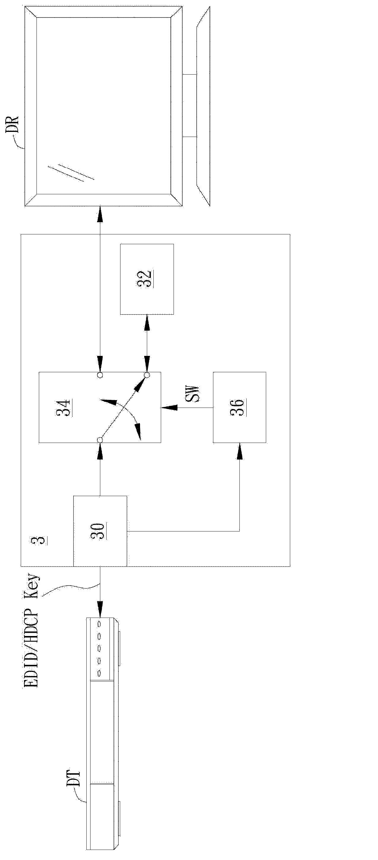
[0037] A preferred embodiment of the present invention is a display data channel switching device. In this embodiment, the display data channel switching device is coupled between the digital image transmitting device and the digital image receiving device. Please refer to image 3 , image 3 is a schematic diagram illustrating the display data channel switching device of this embodiment.

[0038] Such as image 3As shown, the display data channel switching device 3 is coupled between the digital image transmitting device DT and the digital image receiving device DR. The display data channel switching device 3 includes a display data channel (Display Data Channel, DDC) 30 , a storage unit 32 , a switching unit 34 and a judging unit 36 ​​. Among them, the display data channel 30 is coupled to the digital image transmission device DT; the storage unit 32 is coupled to the switching unit 34; the switching unit 34 is coupled to the digital image transmission device DT and the ...


PUM


Abstract

The invention disclsoes a display data channel switching device coupled between a digital image transmitting device and a digital image receiving device. The display data channel switching device comprises a display data channel,a storage unit, a switching unit, and a determination unit. The display data channel can be used to transmit the extension display identification information signals or the high-bandwidth content protection signal golden key. The storage unit is used to storing the extension display identification information data. The determination unit can be used to determine the extension display identification information data or the high-bandwidth content protection signal golden key is transmitted by the display data channel, and can be used to generate the switching signal to the switching unit according to the determination results. The switching unit can be used to couple the digital image transmitting device to the digital image receiving device selectively according to the switching signal.

Description

technical field [0001] The invention relates to the transmission of digital image signals, in particular to a display data channel switching device and a display data channel switching method. Background technique [0002] In recent years, due to the rapid development of multimedia audio-visual technology, various types of multimedia signal transmission systems and multimedia playback and display devices have appeared on the market. For example, if figure 1 As shown, a multimedia playback device 11 with a high-bandwidth digital content protection (High-bandwidth Digital Content Protection, HDCP) protection mechanism can be coupled to a display 12 through a switch 10 . Wherein, the switcher 10 includes an ASIC chip 100 and a microprocessor 102 capable of processing a high-bandwidth digital content protection signal Key (Key) and an Extended Display Identification Data (EDID) signal. However, due to the high cost of using the ASIC chip 100 in the switch 10 , for some low-end...

Claims


Application Information

Patent Timeline
Patent Type & Authority Applications(China)
IPC IPC(8): H04N5/765G09G5/00G09G3/20
Inventor 车建梁洪星
Owner ATEN INT CO
Features
  • R&D
  • Intellectual Property
  • Life Sciences
  • Materials
  • Tech Scout
  • Unparalleled Data Quality
  • Higher Quality Content
  • 60% Fewer Hallucinations
Learn More