


Quick Research
Generate reliable direction feasibility study reports for your R&D in just a few steps.

Technical Q&A
Discover and master advanced knowledge NOW. Basics, ideas, possibilities, all at once.

Find Solutions
As an expert in R&D theories, this can generate solutions to your technical problems instantly.

Evaluate Feasibility
Analyze your overall solution with one click, know your potential R&D risks in advance.

Monitor Landscape
Get weekly tech updates, stay abreast of the latest tech innovations and key insights.
Apparatus for making components by selectively melting powder
A selective, powder-based technology, applied in the field of manufacturing components, can solve the problems of high cost, heavy components, difficult transportation, etc., and achieve the effect of reducing weight and thermal inertia
- Summary
- Abstract
- Description
- Claims
- Application Information
AI Technical Summary
Problems solved by technology
Method used
Image

Examples
Embodiment Construction
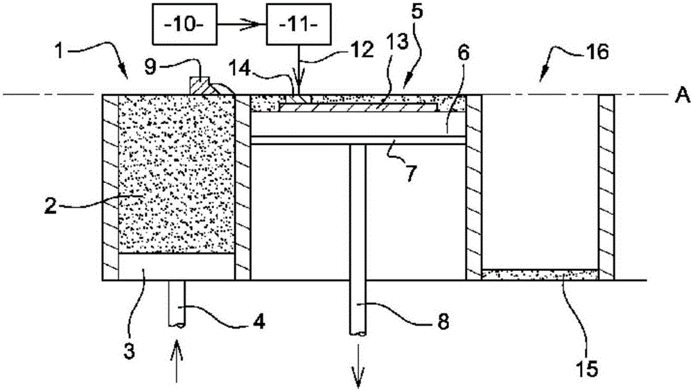
[0028] figure 1 A known apparatus for manufacturing metal parts by selective melting of powder is shown. It comprises: a tank 1 comprising metal powder 2 and having a bottom 3 movable in the direction of vertical translation by means of a rod 4 of an actuator; and an adjacent container 5 in which, Its bottom is formed by a movable plate 6 fastened to a movable support 7 which is likewise movable in the direction of vertical translation by means of a rod 8 of an actuator.
[0029] The device also has a wiper 9 for moving the powder from the tank 1 to the container 5 by moving along the horizontal plane A, and a member 10 for generating a laser beam or an electron beam, which is connected to guide and move the The device 11 of the bundle 12 is connected.
[0030] The steps to make metal parts with the help of this device are as follows:
[0031] First, the bottom 3 of the tank 1 is moved upwards so that a quantity of powder 2 lies on the horizontal plane A. The wiper 9 then ...
PUM
 Abstract
Description
Claims
Application Information
 - R&D Engineer
- R&D Manager
- IP Professional
- Industry Leading Data Capabilities
- Powerful AI technology
- Patent DNA Extraction
Browse by: Latest US Patents, China's latest patents, Technical Efficacy Thesaurus, Application Domain, Technology Topic, Popular Technical Reports.
© 2024 PatSnap. All rights reserved.Legal|Privacy policy|Modern Slavery Act Transparency Statement|Sitemap|About US| Contact US: help@patsnap.com