Air fryer

A technology of air fryer and pot support, which is applied to kitchen utensils, household utensils, roasters/barbecue grills, etc., which can solve the problems of single control function and inability to realize intelligent linkage control, and achieve high thermal efficiency and low power consumption volume effect

Inactive Publication Date: 2014-07-09
ZHEJIANG WUYI WJL PLASTIC IND
View PDF8 Cites 63 Cited by
  • Summary
  • Abstract
  • Description
  • Claims
  • Application Information

AI Technical Summary

Problems solved by technology

[0006] In the fryer control device, similar to the household electric cooker, a control panel is set on the lid, and the control pa

Method used


Image

  • Air fryer
  • Air fryer
  • Air fryer

Examples


Embodiment Construction

[0031] The present invention will be further described below in conjunction with the accompanying drawings.

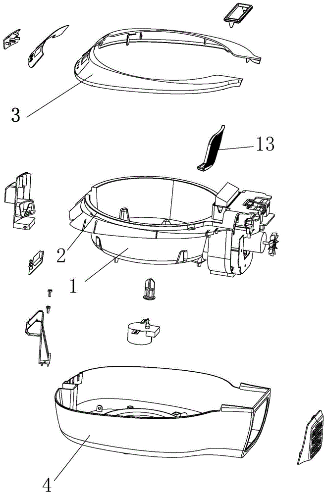
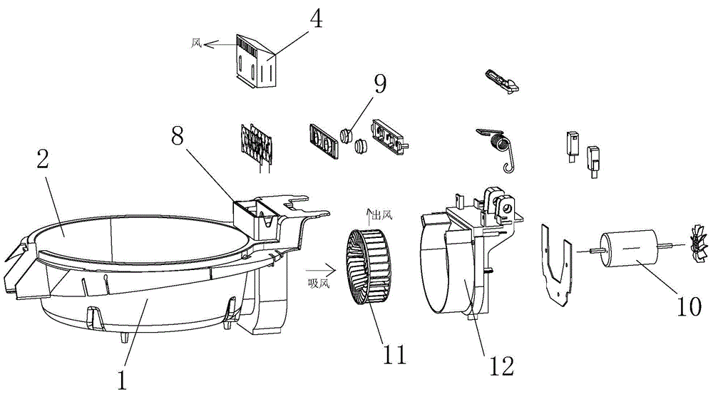
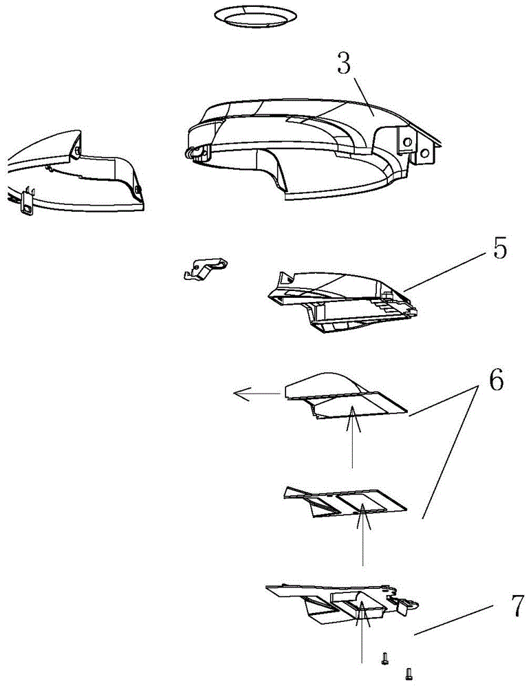
[0032] refer to Figure 1 ~ Figure 3 , an air fryer, comprising a pot frame 1, a pot body 2, a cover 3 and a base 14, the pot body 2 is located in the pot frame 1, the pot frame 1 is located in the base 14, one end of the cover 3 is connected to the The tail of the pot support 1 is hinged, and the other end of the cover 3 is openly connected to the front of the pot support 1. The air fryer also includes a hot air circulation structure, and the hot air circulation structure includes an axial flow fan, a heating wire 4 and a hot air Channel, the axial flow fan is installed in the front part of the pot body 2, the axial air suction port of the axial flow fan is located in the gap between the pot body 2 and the pan frame 1, the axial flow fan The radial air outlet communicates with the lower outlet of the hot air channel, the hot air channel is vertically arranged, and th...


PUM


Abstract

Disclosed is an air fryer which comprises a fryer rack, a fryer body, a cover and a base. The fryer body is located in the fryer rack which is located in the base, and one end of the cover is hinged to the tail of the fryer rack while the other end of the cover is connected with the front of the fryer rack in an openable and closable manner. The air fryer further comprises a hot air circulation structure which comprises an axial flow fan, a wire heater and a hot air passage, the axial flow fan is mounted in the front of the fryer rack, an axial air suction opening of the axial flow fan is located in a hole between the fryer body and the fryer rack, a radial air outlet of the axial flow fan is communicated with an outlet at the bottom of the hot air passage which is disposed vertically and located in the cover, the outlet of the hot air passage is horizontal in direction and communicated with an inner cavity of the fryer body, and the wire heater is located in the hot air passage. The air fryer is capable of effectively lowering power consumption and high in heat efficiency.

Description

technical field [0001] The invention relates to an air fryer. Background technique [0002] The existing air fryer includes a pot frame, a pot body and a cover. The pot frame is provided with a cavity for placing the pot body, the pot body is located in the cavity, and one end of the cover is connected to the pot body. The tail of the rack is hinged, and the other end of the cover is openably connected to the front of the pot rack, and a fryer control device is installed at the front of the pot rack. [0003] The existing cover is provided with a hot air channel from top to bottom, the top of the hot air channel communicates with the atmosphere, the bottom of the hot air channel communicates with the inner cavity of the pot, and the middle part of the hot air channel is equipped with a heating wire. The air pump is installed in the lower part. When hot air is needed, the electric heating wire heats up the cold air brought in by the air pump and introduces it into the pot af...

Claims


Application Information

Patent Timeline
IPC IPC(8): A47J37/06
CPCA47J37/0641
Inventor 王建敏
Owner ZHEJIANG WUYI WJL PLASTIC IND
Why Eureka
Try Eureka