Compressed gas cooling and dehumidification device

A technology for cooling, dehumidifying, and compressing gas, which is applied to the separation of dispersed particles, chemical instruments and methods, and separation methods, and can solve problems such as slowing down of gas, inability to use it directly, and damage to equipment

Active Publication Date: 2016-03-16
陈凤军
View PDF8 Cites 0 Cited by
  • Summary
  • Abstract
  • Description
  • Claims
  • Application Information

AI Technical Summary

Problems solved by technology

[0002] When the device (such as air pump, air compressor, etc.) that can compress the gas and discharge the gas is working, because the volume of the gas shrinks rapidly, the temperature of the gas will increase accordingly (exothermic process), and if this high-temperature gas Direct use is a cooling process in the daily environment. During the use process, a large amount of water will condense, which will cause damage to the equipment and cannot be used directly. It needs to be cooled by a radiator before being discharged, but the cooled air will Contains a large amount of water (liquid water) and cannot be used directly, and it is necessary to discharge the dry, low-temperature gas for use after gas-water separation; in order to achieve the above purpose, traditionally a cooling system driven by a motor is provided for the radiator. fan
On the one hand, this structure needs to provide additional power to drive the motor, which increases the cost. After cooling down, the gas enters the gas-water (liquid) separator (tank), and the space of the gas-liquid separator suddenly increases to slow down the gas and flow in a certain direction. separate air from water
On the other hand, the kinetic energy generated by the high-speed air flowing into the separator is wasted, and its structure is relatively loose, so it takes up a lot of space

Method used


Image

  • Compressed gas cooling and dehumidification device

Examples


Embodiment Construction

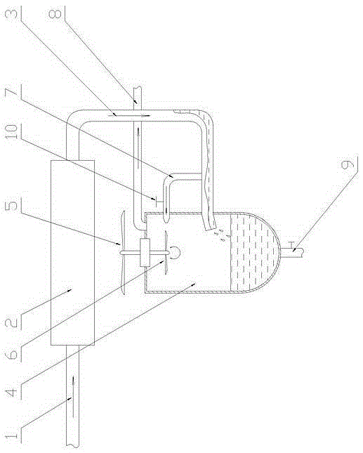
[0009] The specific implementation manner of the present invention will be described below with reference to the accompanying drawings. Such as figure 1 Shown: a compressed gas cooling and dehumidification device, including a radiator 2, one end of the radiator 2 is connected to a high-temperature compressed air pipe 1, and the other end is connected to a gas-water separator 4 through a gas-liquid mixing pipe 3, and the gas-water A cooling fan 5 is supported on the separator 4 through bearing rotation. The position of the cooling fan 5 matches the radiator 2. A power wind wheel 6 that can rotate coaxially with the cooling fan 5 is arranged in the gas-water separator 4. The upper part of the liquid mixing pipe 3 is provided with a power pipe 7, and the outlet of the power pipe 7 is located in the gas-water separator 4, and a speed valve 10 is also arranged on the power pipe 7; the position of the outlet of the power pipe 7 and the power wind wheel 6 To match, a dry air dischar...


PUM


Abstract

The invention discloses a compressed air cooling and dehumidification device, which comprises a radiator (2) connected with a high temperature compressed air pipe (1), and is characterized in that: the radiator (2) is communicated with an air-water separator (4) through an air-liquid mixing pipe (3); a cooling fan (5) is rotatably supported on the air-water separator (4); the cooling fan (5) matches the position of the radiator (2); a power wind wheel (6) coaxial with the cooling fan (5) is disposed in the air-water separator (4); a power pipe (7) communicated with the air-water separator (4) is disposed at the upper part of the air-liquid mixing pipe (3); an outlet of the power pipe (7) matches the position of the power wind wheel (6); a dry air discharge pipe (8) is disposed at the top of the air-water separator (4); and a water discharge pipeline (9) with a valve is disposed at the bottom of the air-water separator (4).

Description

technical field [0001] The invention relates to an auxiliary structure of a compressed gas device, in particular to a compressed gas cooling and dehumidification device. Background technique [0002] When the device (such as air pump, air compressor, etc.) that can compress the gas and discharge the gas is working, because the volume of the gas shrinks rapidly, the temperature of the gas will increase accordingly (exothermic process), and if this high-temperature gas Direct use is a cooling process in the daily environment. During the use process, a large amount of water will condense, which will cause damage to the equipment and cannot be used directly. It needs to be cooled by a radiator before being discharged, but the cooled air will Contains a large amount of water (liquid water) and cannot be used directly, and it is necessary to discharge the dry, low-temperature gas for use after gas-water separation; in order to achieve the above purpose, traditionally a cooling sys...

Claims


Application Information

Patent Timeline
Patent Type & Authority Patents(China)
IPC IPC(8): B01D53/26
Inventor 陈凤军
Owner 陈凤军
Why Eureka
Try Eureka