
High speed railway two-line-to-four-line turnout zone bridge beam portion structure

A technology for high-speed railways and switch areas, applied in bridges, buildings, etc., can solve problems such as poor train safety and comfort, strong train dynamic response, and intensified ground dynamic response, so as to improve safety and comfort, improve power performance, reducing the effect of lateral misalignment

Inactive Publication Date: 2014-07-09
CHINA RAILWAY SIYUAN SURVEY & DESIGN GRP
View PDF0 Cites 0 Cited by
  • Summary
  • Abstract
  • Description
  • Claims
  • Application Information

AI Technical Summary

Problems solved by technology

[0003] 1. The transverse stiffness and torsional stiffness of the multi-piece simply supported T-beam are small, and when a high-speed train passes, the geodynamic response is intensified, and the safety and comfort of the train are poor, which cannot meet the requirements of high-speed railways
[0004] 2. When the girder part of the turnout bridge adopts multi-piece simply supported T-beams, the turnouts cannot be avoided to be arranged on the beam joints. The expansion and contraction of the beam joints, the lateral displacement, and the rotation of the beam ends will all cause changes in the geometric shape of the turnouts. High-speed turnouts Any unevenness beyond the allowable range may arouse a strong dynamic response of the train, which will have an adverse effect on driving safety.
The conventional scheme is to use multiple beams in the horizontal direction, and the main line beams and side line beams are independent of each other. This scheme can meet the requirements in terms of strength and rigidity, but there is still a shortcoming in this scheme, that is, the continuous At the joints where the beams are connected, the lateral dislocation of the rails caused by the deformation of the beams is relatively large, which is difficult to control and difficult to meet the requirements of ballastless tracks for high-speed railways

Method used


Image

  • High speed railway two-line-to-four-line turnout zone bridge beam portion structure
  • High speed railway two-line-to-four-line turnout zone bridge beam portion structure
  • High speed railway two-line-to-four-line turnout zone bridge beam portion structure

Examples


Embodiment Construction

[0021] The present invention will be described in further detail below in conjunction with the accompanying drawings and specific embodiments, so that those skilled in the art can understand.

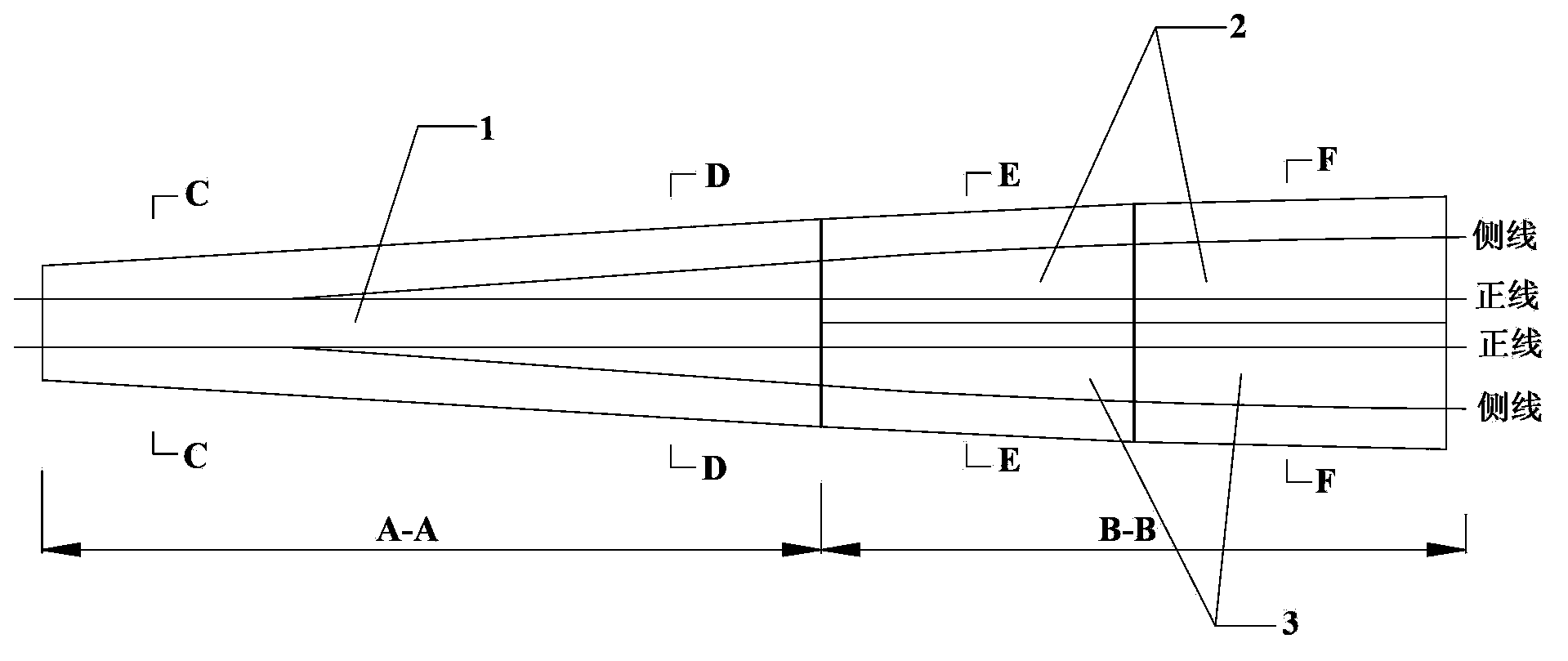
[0022] like figure 1 Shown: the bridge girder structure of the high-speed railway two-line-to-four-line turnout area, including the two-line to four-line turnout area A-A, and the area B-B where the line spacing changes after the switch; the two-line to four-line turnout area A-A) is changed The wide continuous beam (1) is formed; the area (B-B) where the line spacing changes behind the fork is distributed symmetrically with the center line, the left widened simply supported beam (2) and the right widened simply supported beam (3).

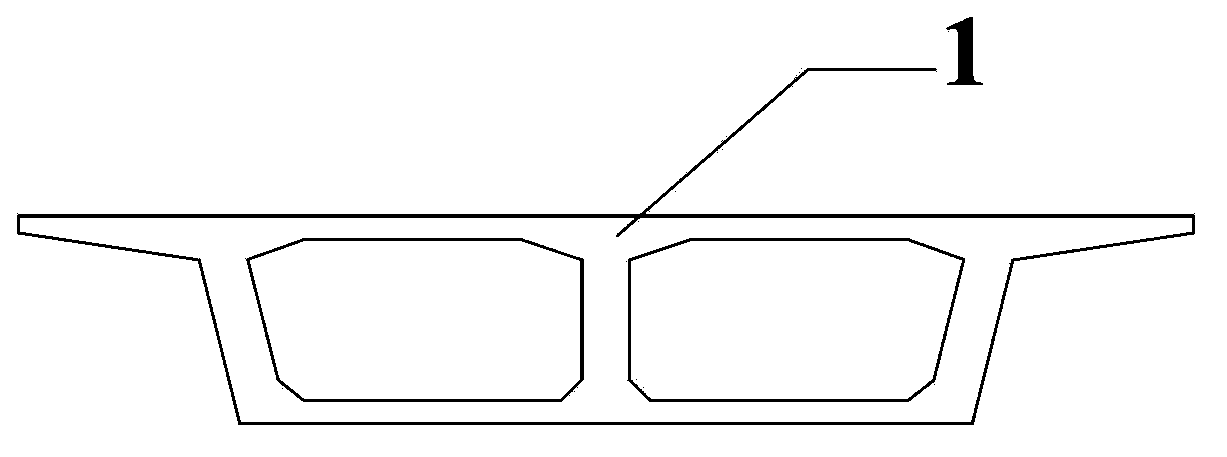
[0023] like Figure 2-4 As shown, the widening continuous beam 1 in the turnout area A-A of the two-line to four-line transformation mainly has two structural forms, one is a box girder with a single box and two chambers, and the other is a box girder with...


PUM


Abstract

The invention discloses a high speed railway two-line-to-four-line turnout zone bridge beam portion structure which comprises a two-line-to-four-line turnout zone and a turnout back line distance change zone. The two-line-to-four-line turnout zone is formed by widening continuous beams, a left widening simple support beam and a right widening simple support beam are symmetrically distributed on the turnout back line distance change zone with a center line as the symmetrical center, and the left widening simple support beam and the right widening simple support beam adopt single-box single-chamber box beams, single-box double-chamber box beams or box beams changing from the single-box single chamber state to the single-box double-chamber state. The beam portion structure adopts the reasonable box chamber structure, improves rigidity of beam bodies, adapts to the turnout zone bridge width and the bridge stress characteristics, improves bridge dynamic performance and improves train running safety and comfortableness.

Description

technical field [0001] The invention relates to the design field of turnout beams in bridges, in particular to a bridge beam structure in a two-line to four-line turnout area of ​​a high-speed railway. Background technique [0002] As a piece of railway equipment, it is quite common to install a turnout on a bridge. The bridge girder in the common railway turnout area adopts a multi-piece simply supported T-beam, which can adapt to the advantage of widening the bridge deck of the bridge in the turnout area. However, there are defects and hidden dangers in the multi-piece simply supported T-beam: [0003] 1. The transverse stiffness and torsional stiffness of the multi-piece simply supported T-beam are small, and when a high-speed train passes, the geodynamic response is intensified, and the safety and comfort of the train are poor, which cannot meet the requirements of high-speed railways. [0004] 2. When the girder part of the turnout bridge adopts multi-piece simply supp...

Claims


Application Information

Patent Timeline
IPC IPC(8): E01D2/04
Inventor 毕玉琢文望青王斌翟润奇许三平陈新吴斌李的平张治华张莉谢晓慧
Owner CHINA RAILWAY SIYUAN SURVEY & DESIGN GRP
Learn More