Universal transfer switch installation components

A transfer switch and installation component technology, applied in the direction of electrical switches, electrical components, circuits, etc., can solve the problems of inconvenient replacement, visual fatigue, single shape, etc., and achieve the effect of saving time, easy identification, and simple structure

Inactive Publication Date: 2016-08-03
SHANGHAI ELECTRICIAN IND & COMMERCE +1
View PDF3 Cites 0 Cited by
  • Summary
  • Abstract
  • Description
  • Claims
  • Application Information

AI Technical Summary

Problems solved by technology

The existing small universal transfer switch installation components are all rectangular and have a single shape, which is easy to cause visual fatigue
In an emergency, if there is no obvious indication on the name plate of the transfer switch, it is very easy to misoperate, which may cause serious accidents.
In addition, the existing mounting components for small universal transfer switches can only meet one installation requirement, so different mounting plates need to be produced for different transfer switches
If the mounting plate of a switch is damaged, it is inconvenient to replace it, so the market needs mounting plates with more shapes and more installation requirements

Method used


Image

  • Universal transfer switch installation components
  • Universal transfer switch installation components
  • Universal transfer switch installation components

Examples


Embodiment 1

[0024] In this embodiment, in order to overcome the lack of a single shape of the universal transfer switch installation component and at the same time ensure that it has multiple installation functions, the following structure is adopted:

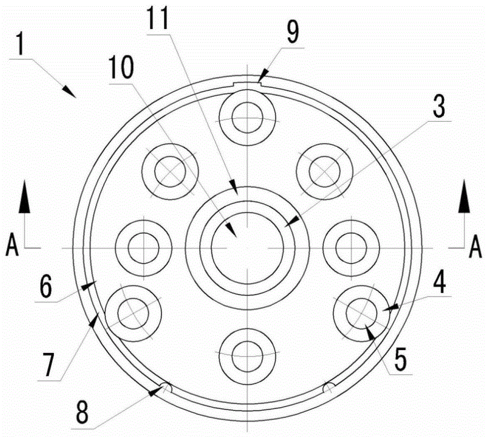
[0025] figure 1 It is a schematic structural diagram of the front view of the installation member of the universal transfer switch of the first embodiment.

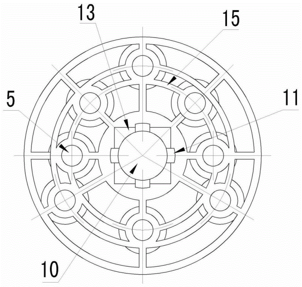
[0026] figure 2 It is a rear view structural schematic diagram of the universal transfer switch installation member of the first embodiment.

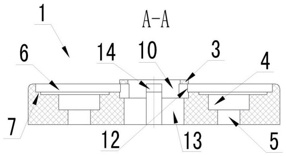
[0027] image 3 It is a schematic diagram of the cross-sectional structure along the A-A direction of the installation member of the universal transfer switch of the first embodiment.

[0028] Such as figure 1 , 2 As shown in and 3 , the universal transfer switch installation member 1 of Embodiment 1 includes a central boss 3 , an annular counterbore 6 , and installation counterbore 4 and installation through hole 5 arranged in an orderly...

Embodiment 2

[0033] In this embodiment, the installation member for the universal transfer switch described in the first example above is used.

[0034] Figure 4 It is a schematic diagram of the assembly and application of the universal transfer switch installation member and the plate in the second embodiment.

[0035] Figure 5 It is a schematic diagram of the assembly and application of the universal transfer switch mounting member and the universal transfer switch in the second embodiment.

[0036] Such as Figure 4 and Figure 5 As shown, during installation, the plate 16 is embedded in the annular counterbore 6 and is in contact with the annular rising step 7, and the side of the plate 16 can be embedded in one of the four rectangular through holes 12 to play a fixing role. The arc-shaped boss 8 is in contact with the edge positioning opening 18 of the name plate 16, which plays the role of positioning and preventing the name plate 16 from twisting, and the arc-shaped notch 9 pl...


PUM


Abstract

The invention relates to a universal diverter switch installation member capable of satisfying multiple installation requirements. The universal diverter switch installation member comprises a central boss, an annular countersunk hole, installation countersunk holes and installation through holes. The central boss is cylindrical-shaped; the annular countersunk hole is circular-shaped; there are at least two installation countersunk holes and at least two the installation through holes, and the installation countersunk holes and the installation through holes are orderly arranged on the upper surface of the annular countersunk hole. The universal diverter switch installation plate provided by the invention solves the problems of similar appearance, single installation requirement and proneness to maloperation of a conventional installation plate in the market and also has the advantages of simple appearance, easy identification, simple structure, convenient operation and the like, thereby satisfying different installation requirements of a miniaturized universal diverter switch.

Description

technical field [0001] The invention relates to a universal switch installation component, in particular to a universal switch installation component capable of meeting various installation requirements. Background technique [0002] A small universal transfer switch is a switching device that can be used for two or more power sources or load conversions. The existing small-sized universal changeover switch mounting components are all rectangular and have a single shape, which easily causes visual fatigue. In an emergency, if there is no obvious indication on the name plate of the transfer switch, misoperation is very likely to occur, which may cause serious accidents. In addition, the existing mounting components for small universal transfer switches can only meet one installation requirement, so different mounting plates need to be produced for different transfer switches. If the mounting plate of a switch is damaged, it is inconvenient to replace it, so the market needs...

Claims


Application Information

Patent Timeline
Patent Type & Authority Patents(China)
IPC IPC(8): H01H9/08
Inventor 潘海峰陈小萍
Owner SHANGHAI ELECTRICIAN IND & COMMERCE
Why Eureka
Try Eureka