Vehicle battery unit

A battery and vehicle technology, applied in the direction of batteries, electrical components, vehicle energy storage, etc., can solve the problems of not considering the inflow, etc., and achieve the effect of lowering the center of gravity, cheap manufacturing, and easy manufacturing

Active Publication Date: 2014-07-09
HONDA MOTOR CO LTD
View PDF10 Cites 8 Cited by
  • Summary
  • Abstract
  • Description
  • Claims
  • Application Information

AI Technical Summary

Problems solved by technology

In addition, in Patent Document 1, the inflow of foreign matter such as garbage from the suction port into the storage battery storage space is not considered.

Method used


Image

  • Vehicle battery unit
  • Vehicle battery unit
  • Vehicle battery unit

Examples


Embodiment Construction

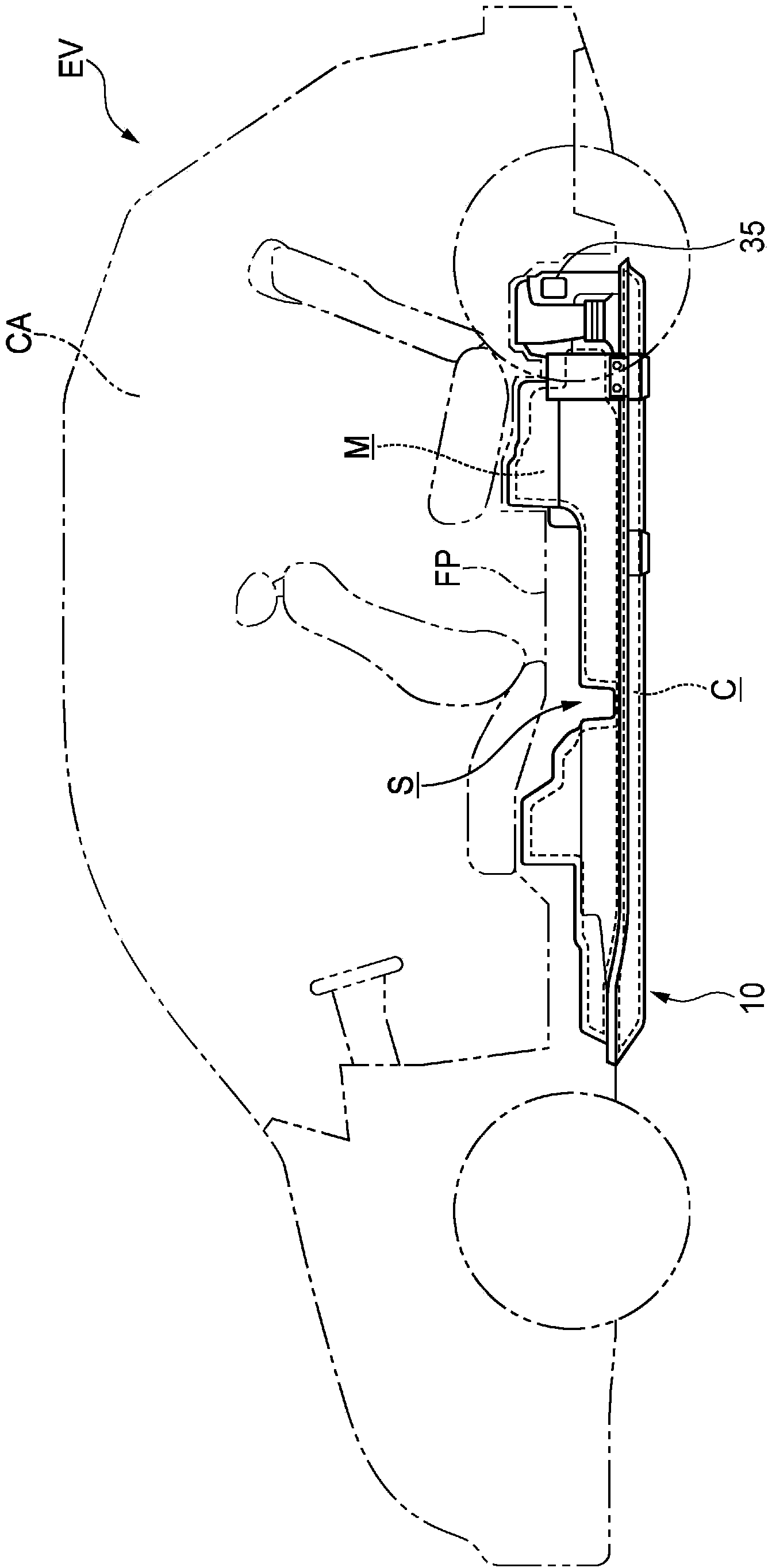
[0053] like figure 1 and figure 2 As shown, the vehicle battery unit 10 according to one embodiment of the present invention is arranged in the underfloor space S located below the floor panel FP of a vehicle, for example, an electric vehicle EV. The underfloor space S is partitioned from the cab CA by the floor panel FP. It should be noted that, as the vehicle, in addition to an electric vehicle, various vehicles capable of running by a motor, such as a hybrid vehicle, can be used.

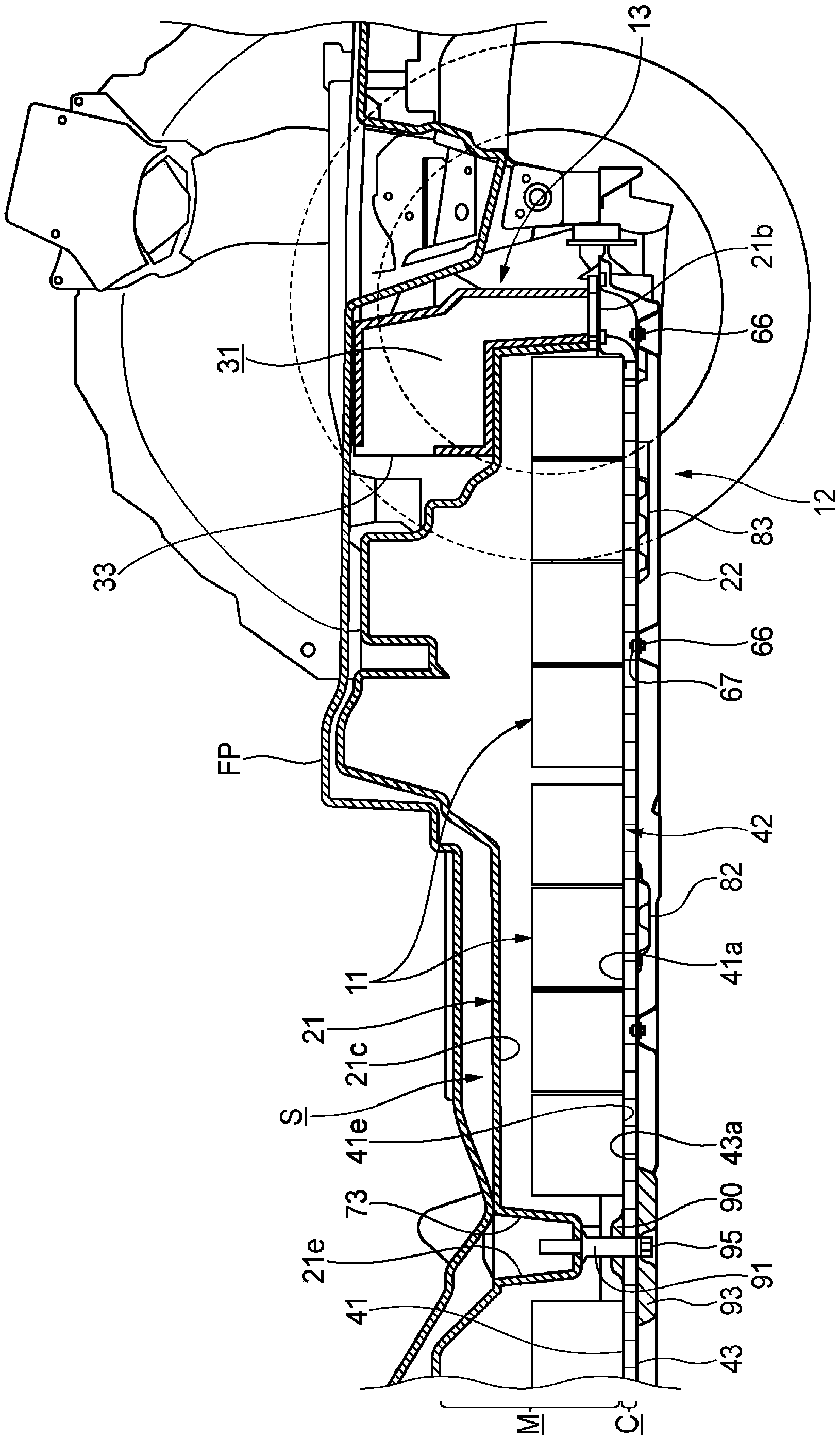
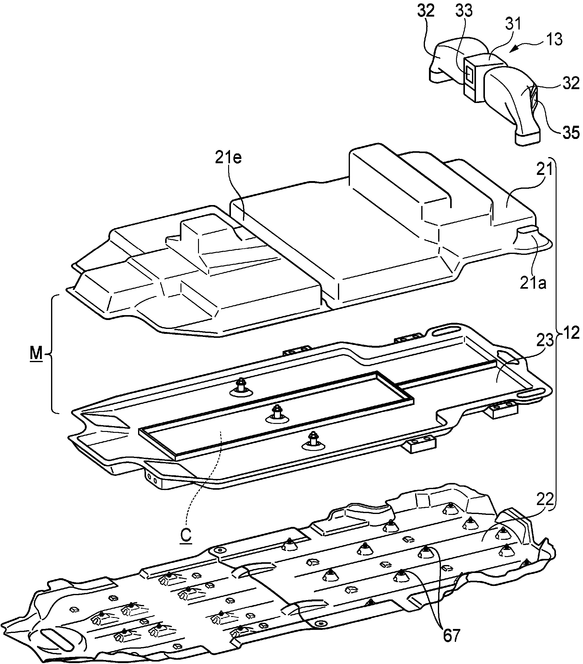
[0054] The battery unit 10 includes a battery 11 , a battery case 12 for accommodating the battery 11 , and a supply and discharge unit 13 attached to the rear and upper portion of the battery case 12 .

[0055] like image 3 As shown, the battery case 12 is formed by an upper cover 21 and a lower cover 22 , and a cooling assembly 23 is provided in the inner space of the battery case 12 formed by the upper cover 21 and the lower cover 22 . The internal space of the battery case 12 is divided...


PUM


Abstract

The invention provides a vehicle battery unit. The battery unit (10) is provided with a battery (11) and a battery case (12) which houses said battery (11) and which is arranged below a floor panel (FP), and the battery (11) is cooled by introducing cooling air from an intake port (33). Inside the battery case (12), a cooling space (C), which communicates with the intake port (33), is formed as a space separate from a battery housing space (M) where the battery (11) is housed.

Description

technical field [0001] The invention relates to a battery unit for a vehicle. Background technique [0002] As a vehicle battery unit used in an electric vehicle or the like, for example, a configuration described in Patent Document 1 is known. In Patent Document 1, the battery unit is arranged under the floor of the vehicle, and an air inlet is provided in front of the battery case having a battery storage space for accommodating the battery. The exhaust port located at the rear of the battery case discharges, and uses the cooling air to directly cool the battery, thereby suppressing the heat generation of the battery. [0003] In addition, Patent Document 1 discloses a structure in which a water absorbing member is disposed above a position where water adhesion should be avoided in consideration of the influence of dew condensation in the battery case, thereby preventing troubles caused by dew condensation. [0004] prior art literature [0005] patent documents [000...

Claims


Application Information

Patent Timeline
Patent Type & Authority Applications(China)
IPC IPC(8): B60K11/06B60K1/04H01M2/10H01M10/613H01M10/625
CPCB60K1/04B60K11/06H01M2220/20B60L1/003Y02T90/16B60K2001/005B60K2001/0438H01M10/625H01M10/6554H01M10/6561H01M10/613H01M10/6563H01M10/6565B60L58/21B60L58/20B60L58/26B60L58/27B60L50/66B60L50/64H01M10/6556Y02T10/70Y02E60/10
Inventor 片山吾一山本康一保户塚康晶
Owner HONDA MOTOR CO LTD
Why Eureka
Try Eureka