Internal high pressure forming die and method of elbow T-branch pipe
A technology for internal high-pressure forming and tee pipes, which is applied in the field of high-pressure forming molds for tee pipes. It can solve problems such as thickening of the bottom of tee pipes, achieve uniform wall thickness, increase forming limit, and reduce compressive stress.
- Summary
- Abstract
- Description
- Claims
- Application Information
AI Technical Summary
Problems solved by technology
Method used
Image
Examples
specific Embodiment approach 1
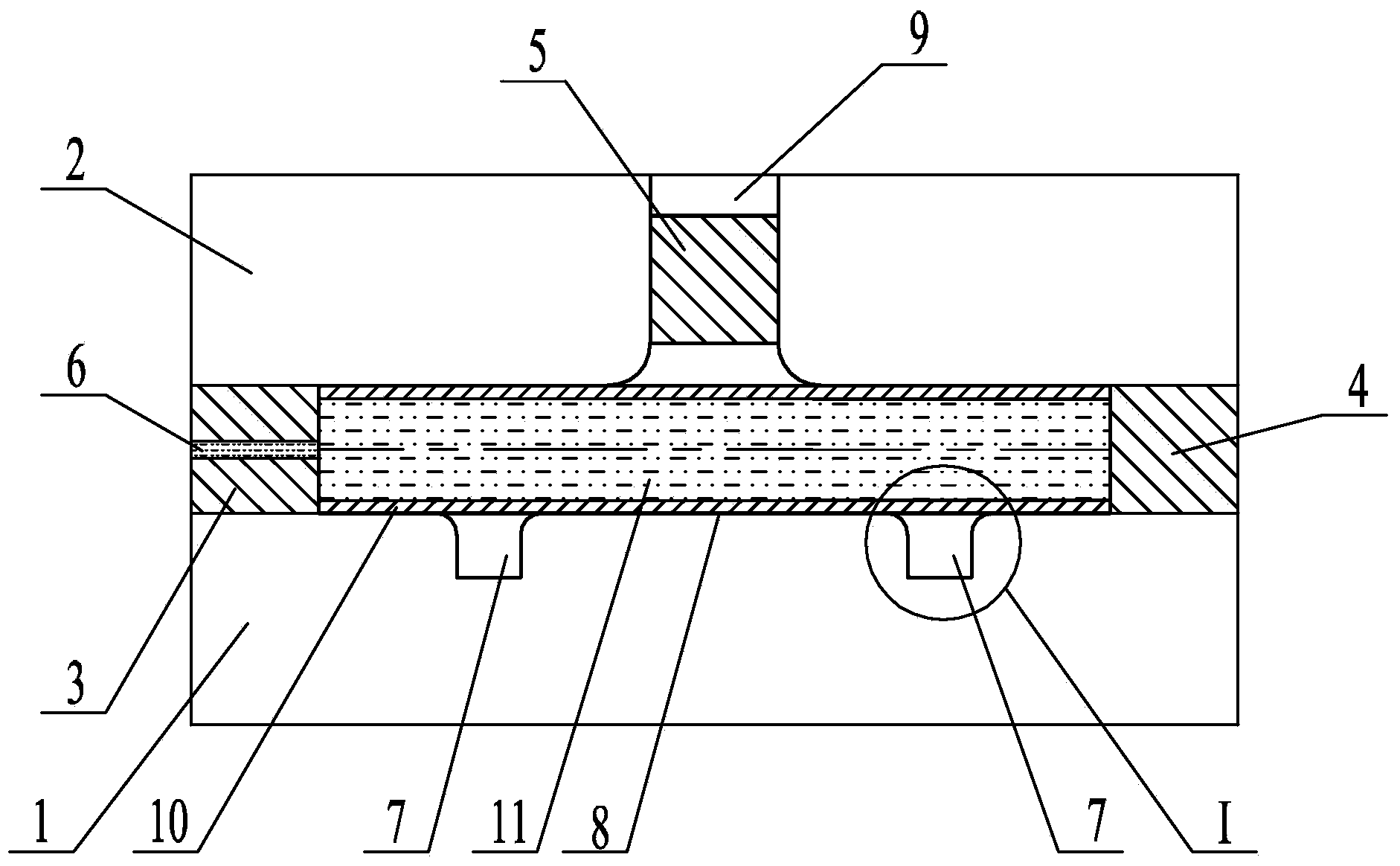
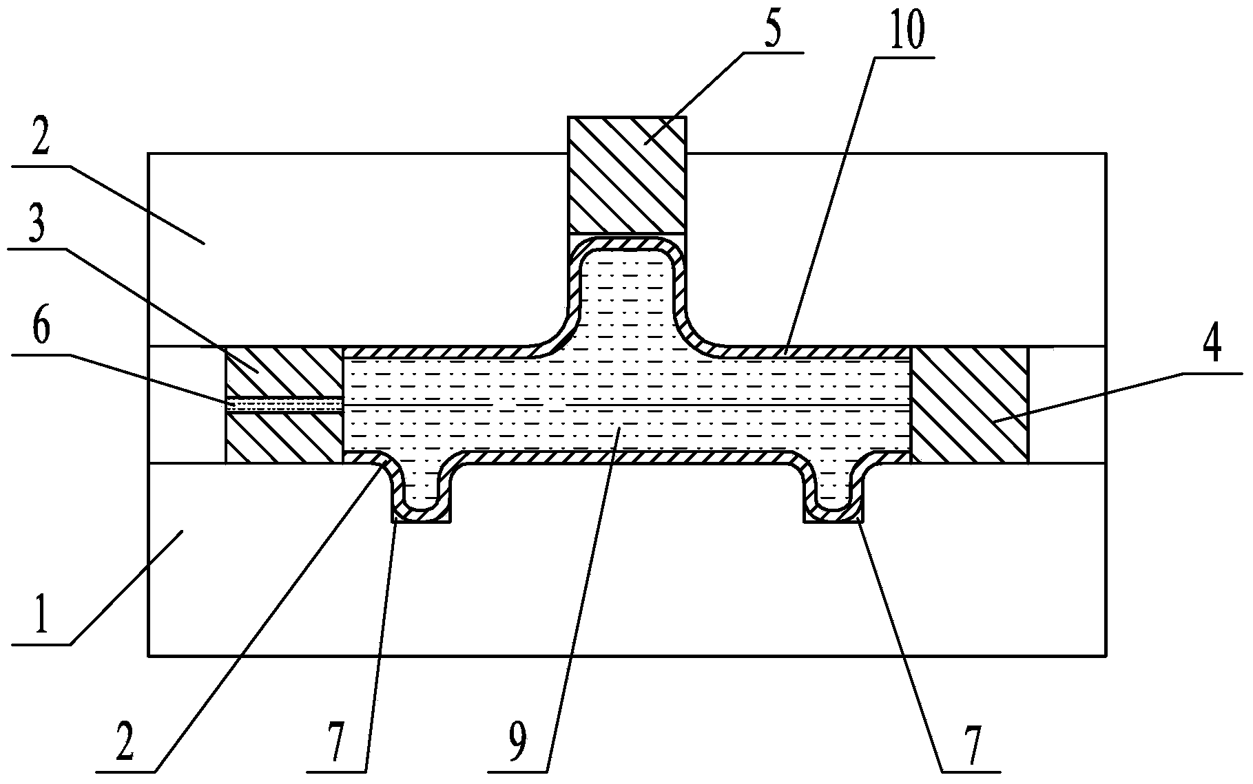
[0036] Specific implementation mode one: combine figure 1 , Figure 6 and Figure 8 Describe this embodiment, this embodiment comprises lower die 1, upper die 2, first punch 3, second punch 4 and intermediate punch 5, upper die 2 and lower die 1 are fastened and set, upper die 2 and lower die A main cavity 8 is arranged between the molds 1, the first punch 3 is set at one end of the main cavity 8, the second punch 4 is set at the other end of the main cavity 8, and the inside of the first punch 3 is provided with a Liquid hole 6, one end of the liquid injection hole 6 communicates with the main cavity 8, the other end of the liquid injection hole 6 is connected with the hydraulic system, the top of the main cavity 8 is provided with a branch cavity 9, and the main cavity 8 is connected to the branch type The cavities 9 communicate with each other, the intermediate punch 5 is arranged in the branch cavity 9, and the bottom of the main cavity 8 is provided with two storage bin...
specific Embodiment approach 2
[0037] Specific implementation mode two: combination Figure 1 to Figure 10 Describe this implementation mode, this implementation mode is realized through the following steps:
[0038] Step 1. Determine the diameter D of the main cavity 8 according to the diameter of the tube blank 10: the diameter D of the main cavity 8 is equal to the diameter of the tube blank 10, see figure 1 and Figure 4 ;
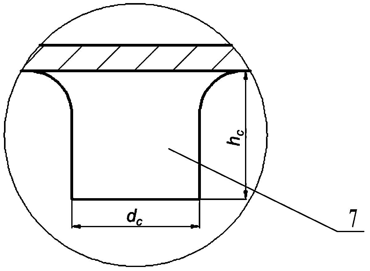
[0039] Step 2: Determine the diameter and depth of the storage bin 7 according to the diameter D of the main cavity 8: the diameter of the storage bin 7 is d c , the depth of storage bin 7 is h c ,See image 3 , the specific calculation formula is as follows:
[0040] d c ≤ ( π + α 2 π ) D or d c ≤ ...
specific Embodiment approach 3
[0049] Specific implementation mode three: combination figure 1 and figure 2 Describe this embodiment, in this embodiment, when the bending angle α=0° of the pipe blank 10 in step 2, the diameter d of the storage bin 7 is calculated according to formula 1 c ≤0.5D, the depth of storage bin 7 is calculated according to formula 2 as h c ≤0.5D. Other steps are the same as in the second embodiment.
PUM
 Abstract
Description
Claims
Application Information
 - R&D
- Intellectual Property
- Life Sciences
- Materials
- Tech Scout
- Unparalleled Data Quality
- Higher Quality Content
- 60% Fewer Hallucinations
Browse by: Latest US Patents, China's latest patents, Technical Efficacy Thesaurus, Application Domain, Technology Topic, Popular Technical Reports.
© 2025 PatSnap. All rights reserved.Legal|Privacy policy|Modern Slavery Act Transparency Statement|Sitemap|About US| Contact US: help@patsnap.com


