
Diesel engine main bearing block and main bearing cap joint face machining method and presetting die plates therefor

A technology for main bearing caps and main bearing housings, which is applied to metal processing equipment, metal processing machinery parts, supports, etc., can solve the problems of low precision, large influence on measurement results, and low processing efficiency, so as to improve accuracy and Efficiency, avoiding the effect of machine tool time loss

Active Publication Date: 2014-07-16
CSSC MES DIESEL
View PDF7 Cites 1 Cited by
  • Summary
  • Abstract
  • Description
  • Claims
  • Application Information

AI Technical Summary

Problems solved by technology

[0006] 1. The processing of each inclined surface of the connecting surface is guaranteed by marking, and the accuracy is not high. Repeated measurement and adjustment processing are required, and the processing efficiency is low.
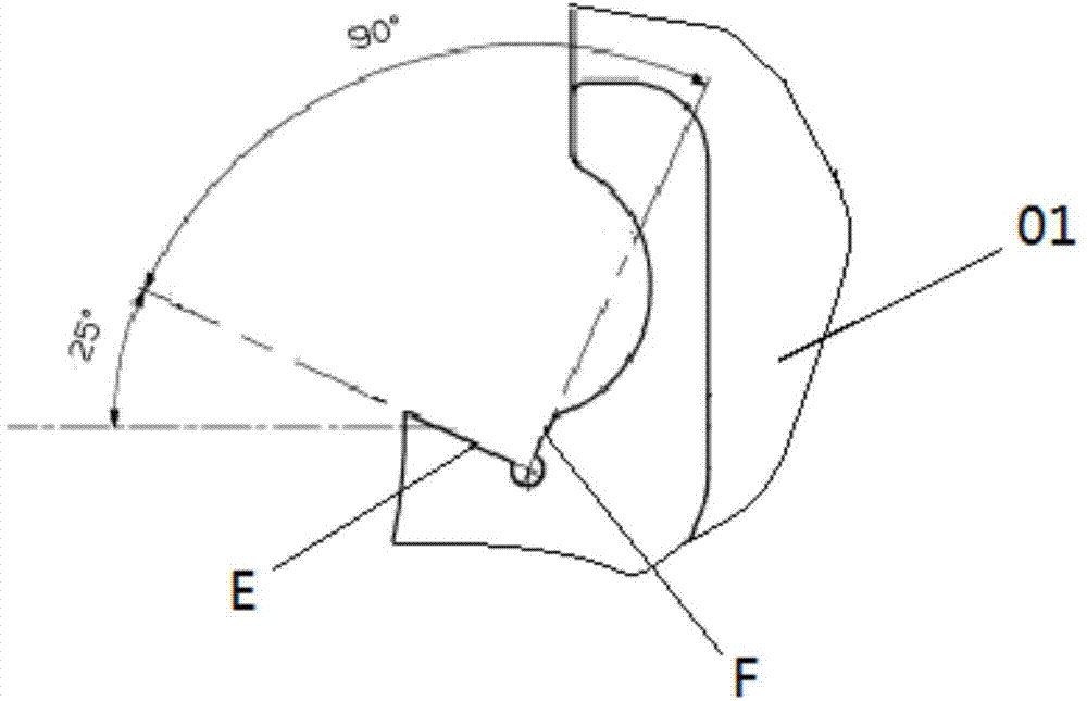
[0007] 2. Use the auxiliary measuring block and the inner diameter micrometer to measure. Due to the large size of the main bearing seat 01 and the main bearing cover 02 of the large low-speed diesel engine, two or three people need to cooperate to complete the operation synchronously. The measurement results are greatly affected by human factors and are easy to Cause overcut and scrap the workpiece
[0008] 3. Even if the main bearing seat 01 and the main bearing cover 02 meet the requirements of the processing drawings when measured after processing, there is still no guarantee that the clearance between the two can meet the requirements after assembly, and they need to be returned to the machine tool for trimming, so the process is cumbersome , low work efficiency

Method used


Image

  • Diesel engine main bearing block and main bearing cap joint face machining method and presetting die plates therefor
  • Diesel engine main bearing block and main bearing cap joint face machining method and presetting die plates therefor
  • Diesel engine main bearing block and main bearing cap joint face machining method and presetting die plates therefor

Examples


Embodiment Construction

[0038] The present invention will be described in further detail below in conjunction with the accompanying drawings and specific embodiments, but the protection scope of the present invention cannot be limited thereby.

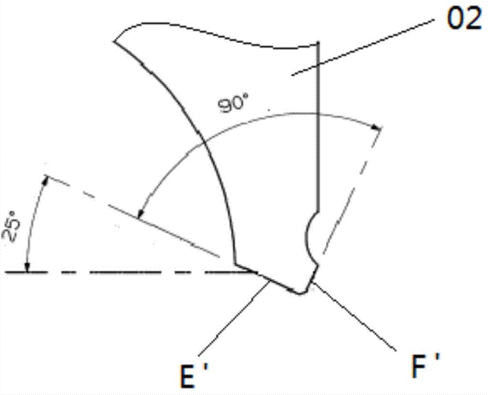
[0039] The processing method described in the present invention is used for the processing of the connection surface between the main bearing seat and the main bearing cover of a large marine low-speed diesel engine, please refer to figure 1 , the connecting surface of the main bearing seat is an inner concave slope, which is composed of two symmetrically distributed slopes E of 25 degrees and two slopes F of 115 degrees, the angle of 25 degrees slope E is 25 degrees with the horizontal plane, and the angle of 115 degree slope F is formed with the horizontal plane 115° angle, i.e. 90° to 25° slope E; see figure 2 , the connecting surface of the main bearing cap is a convex slope, which is also composed of two 25-degree slopes E' and two 115-degree slopes F' ...


PUM


Abstract

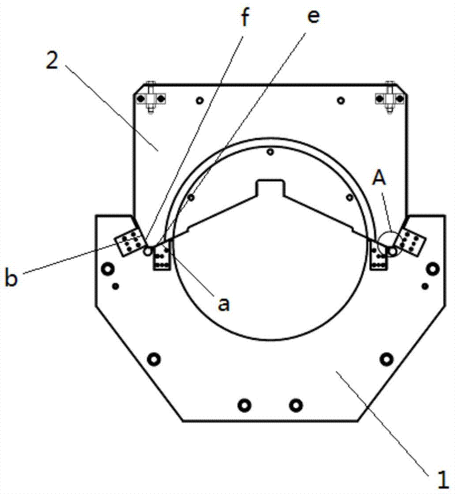
Disclosed are a diesel engine main bearing block and main bearing cap joint face machining method and presetting die plates therefor. Two presetting die plates in conformity to features of main bearing block and main bearing cap joint faces are adopted. The presetting die plates are provided with two 25-degree presetting slants and two 115-degree presetting slants which are symmetric; the slants of the presetting die plates are in conformity to 25-degree slants and 115-degree slants of a main bearing block and a main bearing cap in terms of position, shape and size; the position, shape and size of the slants of the presetting die plates meet the corresponding requirements for tolerance in shape and size. The presetting die plates are paired, finished and machined, so that the requirement for a fitting gap between the main bearing block and main bearing cap joint faces is met, the requirement for the gap between the joint faces during assembly is also met, accuracy and effectiveness in machining are greatly improved, waste on machine-hour and labor and risk of workpiece scrapping are avoided.

Description

technical field [0001] The invention relates to the processing of a large low-speed diesel engine, in particular to a method for processing the connecting surface of a main bearing seat of a diesel engine frame and a main bearing cover and a tool setting template for realizing the method, belonging to the technical field of diesel engine manufacturing. Background technique [0002] The main shaft of a large low-speed diesel engine is supported between the main bearing seat and the main bearing cover, and the main bearing cover and the main bearing seat are combined through the connecting surface. see figure 1 , the connecting surface of the main bearing seat is an inner concave slope, which is composed of two symmetrically distributed 25-degree slopes E and two 115-degree slopes F, the 25-degree slope E forms an angle of 25° with the horizontal plane, and the 115-degree slope F forms an angle of 115° with the horizontal plane angle, that is, an angle of 90° to the 25° slope...

Claims


Application Information

Patent Timeline
IPC IPC(8): B23Q3/18
CPCB23Q15/22
Inventor 王巍倪杰张伟
Owner CSSC MES DIESEL
Learn More