Airless tires with built-in tube rings and hoops

A technology of non-pneumatic tires and round tubes, applied in the direction of wheels, wheel covers, transportation and packaging, etc., can solve the problems of uneven ground contact of tires, permanent reduction of foam cells, unsuitable for heavy-duty driving, etc., to improve the bearing capacity and elasticity, reducing the internal temperature rise, reducing the effect of materials

Active Publication Date: 2016-12-28
SUZHOU XINENG ENVIRONMENTAL SCI & TECH CO LTD
View PDF8 Cites 0 Cited by
  • Summary
  • Abstract
  • Description
  • Claims
  • Application Information

AI Technical Summary

Problems solved by technology

[0002] The first major defect of existing air-free tires is that the tire hoop is not tight enough to the rim, causing the tire to separate from the rim and slide relative to the rim, which is not suitable for high-speed or heavy-duty driving. The second major defect is that the tire It is foamed, and the cells become permanently smaller after being pressed, causing the tire to sag, resulting in uneven and enlarged contact surface of the tire, and increased driving jitter and rolling resistance of the vehicle

Method used


Image

  • Airless tires with built-in tube rings and hoops
  • Airless tires with built-in tube rings and hoops
  • Airless tires with built-in tube rings and hoops

Examples


Embodiment 1

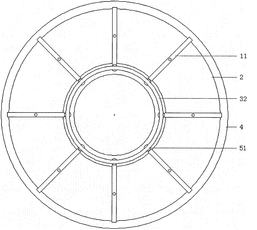
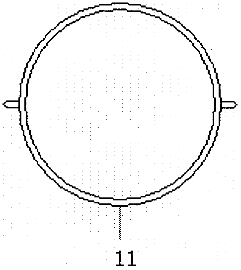
[0008] Embodiment one, such as Figure 1 to Figure 3.1 , Figure 4.1 , Figure 5 , Figure 6 As shown: eight closed connecting cylinders 11 or open connecting cylinders 12 with two outer walls connected to reverse columns are equally spaced on the pipe surface of a circular pipe ring 2, and the reverse columns of the connecting cylinders are all parallel to The rotating shaft of the circular tube ring (that is, the opposite column supports the two side walls of the circumference of Ω, so that the circular tube ring does not produce axial displacement in the mold cavity), together with a spring hoop 41, is placed in the cavity of the two-petal mold Inside, the cavity wall above the lower part of the cross section of the mold cavity 4 forms an Ω circle, and the lower wall is provided with eight groups of equally spaced, two-to-two facing single-end support ring column groups 51 whose length direction is perpendicular to the rotation axis of the Ω ring. The coincidence of the ...

Embodiment 2

[0009] Embodiment two, such as Figure 1 to Figure 3.1 , Figure 4.1 , Figure 7 , Figure 8 Shown: Figure 7 , Figure 9 The connecting cylinder shown is the slotted connecting cylinder 12 and the open connecting cylinder 13, and the two single steel wire rings 70 are symmetrically embedded in the top inner wall groove of the open connecting cylinder or the inner peripheral wall of the slotted connecting cylinder The end of the single steel wire ring is welded or pipe-connected. According to the embedding method, it can also be placed in the two-part mold of the special-shaped circular pipe ring with a conjoined reverse column or reverse ring rib to achieve plastic bonding. The ends of the single-piece steel wire ring are welded or piped. Others are the same as in Embodiment 1.

Embodiment 3

[0010] Embodiment three, such as Figures 1 to 4.2 , Figure 9 to Figure 13 Shown: Figure 10 , Figure 11 The hoop shown is that the elastic tube hoop 32 is embedded in the groove of the single-ended groove support ring column group 51. The elastic tube hoop is formed by placing a long-pitch coil spring in a plastic tube and then connecting the two ends of the spring. Figure 12 , Figure 13 The spacer posts shown are double groove spacer post sets 52, Figure 12 A spring hoop 31 is respectively embedded in each opposite groove of the double-slot support ring post group, Figure 13 A bomb tube hoop 32 is respectively embedded in each opposite groove of the double groove support ring post group, Figure 9 The top ring side formed by the top surface of the peripheral wall of the opening connected to the cylinder 13 is provided with a composite ring 71 of this material, Figure 10 The top ring side formed by the top surface of the peripheral wall of the slit connected with...


PUM


Abstract

Disclosed is a non-pneumatic tire with built-in round pipe ring and hoop. The non-pneumatic tire comprises a connected outer tire, the pipe surface of the round pipe ring sleeves at least three connected column barrels at equal intervals, two outer side walls of each of the at least three connected column barrels are connected with reverse columns, the reverse columns of the connected column barrels are parallel to a rotating shaft of the round pipe ring, at least one elastic hoop is together placed in a die cavity of a two-section die, upper cavity walls of the cross section of the die cavity are in an omega-shaped circumference, at least three groups of supporting rings which are pairwise opposite, arranged at equal intervals and vertical to an omega round ring rotating shaft are arranged on lower wall surfaces of the die cavity, at least one of same direction ends of the supporting ring groups is provided with a groove, the middle ring line of the round pipe ring coincides with the round ring of the omega-shaped cross section of the die cavity, each elastic hoop is embedded into one groove of same direction supporting ring columns, thereby, the largest circle ring and the smallest circle ring formed by the supporting ring columns and the connected column barrels around the rotating shaft of the round pipe ring can coincide, a liquid colloidal high molecular material is poured into the cavity to form the connected outer tire, and the non-pneumatic tire can be obtained.

Description

technical field [0001] The invention is about the invention of the air-free tire with built-in circular tube ring and hoop. Background technique [0002] The first major defect of existing air-free tires is that the tire hoop is not tight enough to the rim, causing the tire to separate from the rim and slide relative to the rim, which is not suitable for high-speed or heavy-duty driving. The second major defect is that the tire It is foamed. After being pressed, the cells become permanently smaller and cause the tire to sag, resulting in uneven and enlarged contact surface of the tire, and increased driving jitter and rolling resistance of the vehicle. Contents of the invention [0003] A non-pneumatic tire with a built-in circular tube ring and hoop, including a conjoined carcass, at least three connecting columns connected to the opposite column on both outer walls are equally spaced on the tube surface of a circular tube ring and connected to the column The reverse col...

Claims


Application Information

Patent Timeline
Patent Type & Authority Patents(China)
IPC IPC(8): B60B7/00
Inventor 全解生
Owner SUZHOU XINENG ENVIRONMENTAL SCI & TECH CO LTD
Why Eureka
Try Eureka