Mechanical and hydraulic integrated dynamic compaction machine

An integrated, dynamic compaction machine technology, applied in mechanical equipment, fluid transmission devices, soil protection, etc., can solve the problems of main winch and brake belt damage, damage to heavy objects, brake belt wear, etc. Scope of application, accident avoidance, cost-saving effect

Active Publication Date: 2014-07-16
BEIJING CSR TIMES LOCOMOTIVE & ROLLING STOCK MECHANICS
View PDF5 Cites 16 Cited by
  • Summary
  • Abstract
  • Description
  • Claims
  • Application Information

AI Technical Summary

Problems solved by technology

[0005] However, when the point braking friction belt is working, the braking force is intermittent and extremely unstable, so that the heavy object cannot be lowered smoothly, and the heavy object may be damaged when it reaches the ground.
On the other hand, the wear and heat of the brake belt are very serious, which will damage the main winch and the brake belt, and the point brake function cannot be used for a long time.

Method used


Image

  • Mechanical and hydraulic integrated dynamic compaction machine
  • Mechanical and hydraulic integrated dynamic compaction machine

Examples


Embodiment Construction

[0032] The core of the present invention is to provide a machine-hydraulic integrated dynamic compaction machine, the dynamic compaction machine main winch has relatively good stability in lowering and lowering the main winch.

[0033] In order to enable those skilled in the art to better understand the technical solutions of the present invention, the present invention will be further described in detail below in conjunction with the accompanying drawings and specific embodiments.

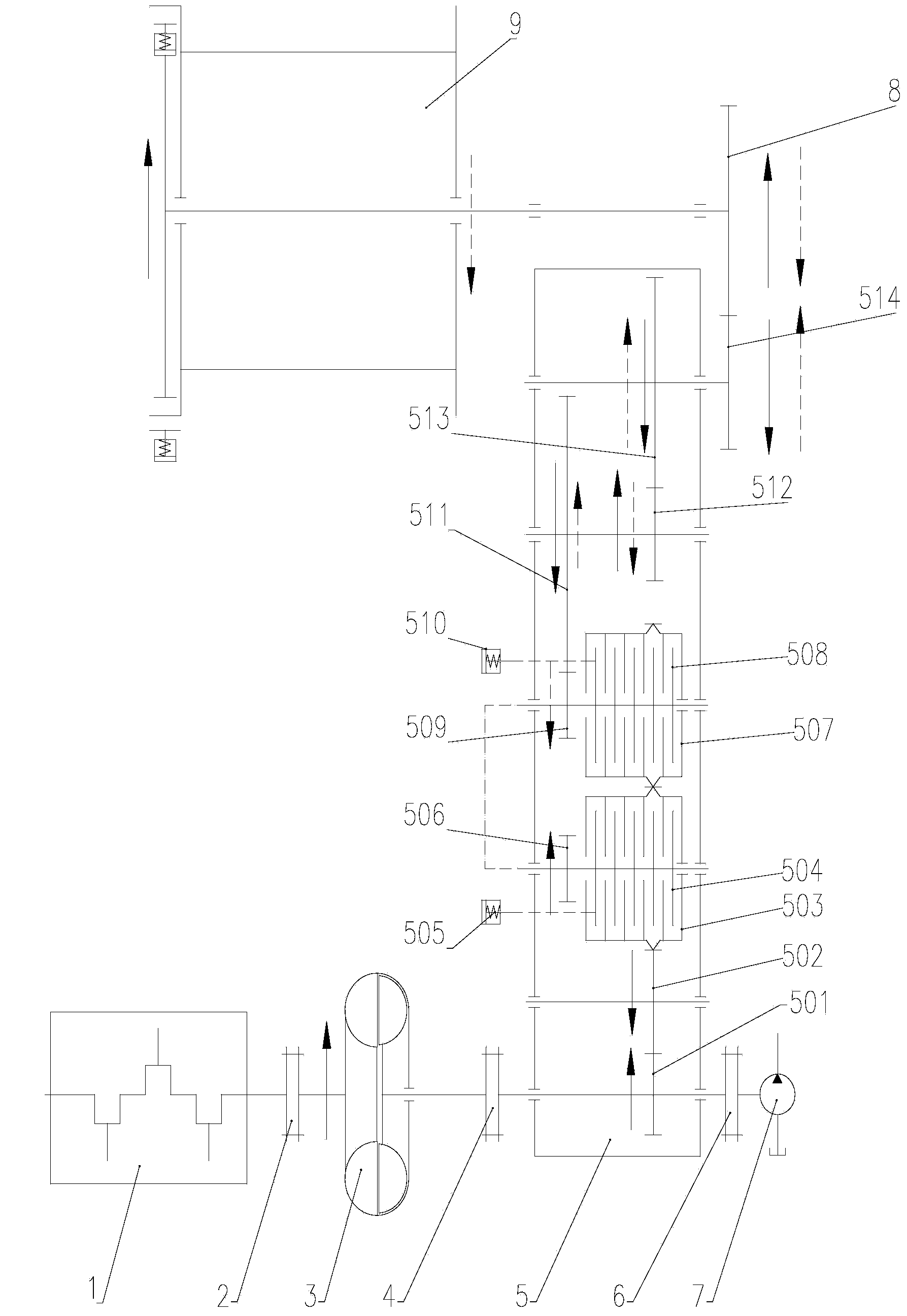
[0034] Please refer to figure 1 , figure 1 It is a structural schematic diagram of a transmission device for a mechanical-hydraulic integrated dynamic compaction machine in a specific embodiment of the present invention.

[0035] The machine-liquid integrated dynamic compaction machine in the present invention comprises engine 1, main hoist 9, walking system, hydraulic system and transmission system for driving the movement of walking system; transmission system includes transfer case connected w...


PUM


Abstract

The invention discloses a mechanical and hydraulic integrated dynamic compaction machine. The mechanical and hydraulic integrated dynamic compaction machine comprises an engine, a main winch, a walking system, a hydraulic system driving the walking system to act, and a transmission system, wherein the transmission system comprises a transfer case which is connected with an output shaft of the engine, power of the engine is transmitted to the main winch and the hydraulic system of the dynamic compaction machine through the transfer case, a first speed reducing assembly is arranged in the transfer case, and the engine is connected with the main winch through the first speed reducing assembly so that the main winch can be driven to rotate in the positive direction; a second speed reducing assembly is further arranged in the transfer case, and the engine is connected with the main winch through the second speed reducing assembly so that the main winch can be driven to rotate in the reverse direction. According to the mechanical and hydraulic integrated dynamic compaction machine, the engine can drive the main winch to rotate in the reverse direction, then a tamper or a weight is driven to be placed downwards, and the tamper can be placed downwards quite stably due to the fact that the engine drives the winch to rotate continuously; in addition, the application flexibility of the machine is further improved due to the fact that a heavy load can be placed down by the dynamic compaction machine, and cost of devices used on a construction site can be reduced to a certain degree.

Description

technical field [0001] The invention relates to the technical field of dynamic ramming machines, in particular to a mechanical-hydraulic integrated dynamic ramming machine. Background technique [0002] According to the different transmission modes of the dynamic compactor, the dynamic compactor can be divided into the following categories: full hydraulic transmission, full mechanical transmission and machine-hydraulic integrated transmission. Among them, the mechanical-hydraulic integrated transmission combines the advantages of mechanical transmission and hydraulic transmission. The main winch transmission of dynamic tamping adopts mechanical transmission, and other working actions adopt hydraulic transmission. It is the most widely used transmission mode of dynamic tamping machine at present. . [0003] The machine-hydraulic integrated transmission device includes the engine, transfer case, main winch, hydraulic system and other working parts. The power of the engine is ...

Claims


Application Information

Patent Timeline
Patent Type & Authority Applications(China)
IPC IPC(8): E02D3/046F16H47/00
Inventor 吴斌谢勇谋周辉刘冲赵锟孙德胜苏冲肖勇李均良聂刚
Owner BEIJING CSR TIMES LOCOMOTIVE & ROLLING STOCK MECHANICS
Why Eureka
Try Eureka