Eureka AIR delivers breakthrough ideas for toughest innovation challenges, trusted by R&D personnel around the world.

Novel air source heat pump heat exchange system

A technology of air source heat pump and heat exchange system, which is applied in the direction of lighting and heating equipment, evaporator/condenser, fluid circulation arrangement, etc., to achieve the effect of long service life of equipment

Inactive Publication Date: 2014-07-16
FUJIAN QIANGMIN AIR SOURCE AUTOMATION TECH
View PDF5 Cites 2 Cited by
  • Summary
  • Abstract
  • Description
  • Claims
  • Application Information

AI Technical Summary

Problems solved by technology

After the power is turned on, the axial flow fan starts to run, and the outdoor air passes through the evaporator for heat exchange, and the cooled air is discharged by the axial flow fan. The R22 low-pressure refrigerant gas is compressed into a high-temperature, high-pressure liquid and sent to the condenser, and the water or wind below 70°C circulated by the pump is forced to exchange heat through the condenser, and the refrigerant working condition after heat exchange is condensed into a medium temperature ( 50-70℃) high-pressure (1.5-3MPA) liquid, medium-temperature high-pressure liquid and then throttling through the expansion valve to become low-temperature and low-pressure gas, the low-temperature and low-pressure gas returns to the evaporator to absorb heat and then enters the heat pump reciprocating cycle. If the medium-temperature heat pump condensing temperature exceeds The pressure of the high-temperature condenser at 70-80°C exceeds 4MPA high pressure, and the pressure limit load of the compressor (3.5-4MPA). Under the action of the overload protection mechanism, the compressor stops working, which causes the heat exchange method to limit the heat exchange. The temperature of hot water or hot air cannot exceed 80°C, which is the bottleneck for the development of new products with existing heat pump technology

Method used


Image

  • Novel air source heat pump heat exchange system

Examples


Embodiment 1

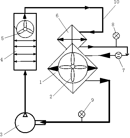
[0013] Embodiment one: if figure 1 As shown, a new type of air source heat pump heat exchange system includes a heat pump unit, the heat pump unit includes an evaporator assembly, a compressor 3, a condenser assembly and a throttling device 7, and the evaporator assembly includes an evaporator 1, an installation Heat exchange fan 2 on the evaporator, a second condenser 6 covered on the evaporator 1, the condenser assembly includes a condenser 4 and a fan 5 arranged on the condenser, the evaporator 1, compressor 3 , the condenser 4 , the second condenser 6 and the throttling device 7 are sequentially connected end to end through a pipeline 10 to form a circulation loop, and a refrigerant circulates in the pipeline 10 .

[0014] In this embodiment, a high pressure gauge 8 is provided on the pipeline 10 between the second condenser 6 and the throttling device 7, and the high pressure gauge 8 monitors the pressure of the refrigerant in the pipeline. When the pipeline pressure exce...


PUM


Abstract

The invention relates to a novel air source heat pump heat exchange system which comprises a heat pump unit. The heat pump unit comprises an evaporator assembly, a compressor, a condenser assembly and a throttling device. The evaporator assembly comprises an evaporator, a heat exchange fan installed on the evaporator, and a second condenser arranged on the evaporator. The condenser assembly comprises a condenser and a driving device arranged on the condenser. The evaporator, the compressor, the condenser, the second condenser and the throttling device are sequentially connected end to end through pipelines to form a circulation loop, and cold media flow in the pipelines. By the utilization of the novel air source heat pump heat exchange system, the temperature of condensate water (condensate wind) can be higher than 80 DEG C, the highest temperature can reach more than 100 DEG C, energy conservation and environmental protection are achieved, and various products for different purposes can be developed.

Description

technical field [0001] The invention relates to a novel air source heat pump heat exchange system. Background technique [0002] The existing heat pump heat exchange system consists of a compressor, a heat exchanger, an axial flow fan, an expansion valve, and an electronic automatic temperature controller. After the power is turned on, the axial flow fan starts to run, and the outdoor air passes through the evaporator for heat exchange, and the cooled air is discharged by the axial flow fan. The R22 low-pressure refrigerant gas is compressed into a high-temperature, high-pressure liquid and sent to the condenser, and the water or wind below 70°C circulated by the pump is forced to exchange heat through the condenser, and the refrigerant working condition after heat exchange is condensed into a medium temperature ( 50-70℃) high-pressure (1.5-3MPA) liquid, medium-temperature high-pressure liquid and then throttling through the expansion valve to become low-temperature and low...

Claims


Application Information

Patent Timeline
IPC IPC(8): F25B39/00F25B41/00F25B41/40
Inventor 真强寿
Owner FUJIAN QIANGMIN AIR SOURCE AUTOMATION TECH
Why Eureka
Eureka Blog
Learn More