Supercharge Your Innovation With Domain-Expert AI Agents!

rolling bearing

A technology for rolling bearings and bearing inner rings, applied in the field of rolling bearings, can solve problems such as high manufacturing costs, large coating equipment and electroplating pools, and economical manufacturing

Active Publication Date: 2017-04-12
SCHAEFFLER TECH AG & CO KG
View PDF8 Cites 0 Cited by
  • Summary
  • Abstract
  • Description
  • Claims
  • Application Information

AI Technical Summary

Problems solved by technology

Of course, the coating required for this can only be applied economically in the case of smaller rolling bearings with an inner diameter of approximately 50 mm to 460 mm, while larger bearings (eg up to a diameter of 3000 mm) cannot be economically applied in this way Manufactured efficiently, since the coating equipment and plating tanks required for this are very large
Furthermore, a large number of poles with a pole width of 500 μm has to be produced, which can only be achieved gradually
For larger bearings, the coding time required to generate the gage becomes very large, resulting in high manufacturing costs

Method used


Image

  • rolling bearing

Examples


Embodiment Construction

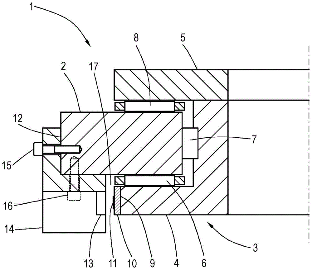
[0016] The rolling bearing 1 shown in the drawing comprises a fixed bearing outer ring 2 and a bearing inner ring 3 which is rotatable relative to the bearing outer ring 2 . The bearing inner ring 3 essentially comprises an angular ring 4 which is connected to an angular disc 5 . As shown in the figures, the angle ring 4 and the shaft disc 5 together approximately form a C-shaped profile, which includes raceways for the rolling bodies 6 , 7 , 8 . The rotatable bearing inner ring 3 is mounted rotatably in the bearing outer ring 2 via rolling elements 6 , 7 , 8 .

[0017] The angle ring 4 has an annular cylindrical contact surface 9 for the measuring ring 10 . The measuring ring 10 is connected to the bearing inner ring 3 , more precisely to the angle ring 4 by means of a force fit. The measuring ring 10 has an inductively detectable measuring standard 11 on its outer side. In the exemplary embodiment shown, measuring standard 11 comprises a plurality of parallel axial stripe...


PUM


Abstract

The invention relates to a rolling bearing having a bearing inner ring (3) and a bearing outer ring (2) movable relative to each other and mounted either on the bearing inner ring or on the bearing outer rings (3, 2) A measuring tool (11), which can be detected by a sensor (13) installed on the other bearing ring (2, 3). According to the invention, a rolling bearing (1) comprises a measuring ring (10) with a gauge (11), which is fastened on the bearing inner ring (3) or on the bearing outer ring (2).

Description

technical field [0001] The invention relates to a rolling bearing, which has a bearing inner ring and a bearing outer ring that can move relative to each other, a measuring tool mounted on either the bearing inner ring or the bearing outer ring, the measuring tool can be installed on another The sensor on the bearing ring to detect. Background technique [0002] Rolling bearings of this type are used, for example, for round tables in machine tools. This is a highly dynamic direct drive for milling or turning workpieces. The rotary table is driven by means of a torque motor and associated converter and regulator. For milling and turning operations, the measuring system preferably has high accuracy and angular resolution, wherein both optical and magnetoresistive angle measuring systems are provided. [0003] The applicant has produced cylindrical bearings marked YRT or YRTM, in which the outer ring of the bearing (also marked housing ring) is screwed to the machine base or...

Claims


Application Information

Patent Timeline
Patent Type & Authority Patents(China)
IPC IPC(8): F16C33/64F16C41/00F16C19/38
CPCF16C41/007F16C19/381F16C2300/14F16C2322/39F16C41/00G01B7/003
Inventor 冈特·施密特于尔根·希尔宾格
Owner SCHAEFFLER TECH AG & CO KG
Features
  • R&D
  • Intellectual Property
  • Life Sciences
  • Materials
  • Tech Scout
  • Unparalleled Data Quality
  • Higher Quality Content
  • 60% Fewer Hallucinations
Learn More