Device and method for measuring azimuth angle and rotating speed of wind wheel of wind turbine based on ball switch

A technology of ball switch and measuring device, which is applied to wind power generators, engines, wind power generation, etc., can solve the problems of increasing the load of wind turbine towers, easy damage of induction detection devices, and low stability of detection systems, and achieves simple structure and realization Easy, high-accuracy measurement results

Active Publication Date: 2021-12-17
CRRC WIND POWER(SHANDONG) CO LTD
View PDF7 Cites 0 Cited by
  • Summary
  • Abstract
  • Description
  • Claims
  • Application Information

AI Technical Summary

Problems solved by technology

[0004] The inventor found that the existing method for detecting the speed of the wind turbine rotor of a wind turbine adopts electromagnetic induction detection. On the one hand, the detection equipment is relatively large, and the wind turbine tower is added On the other hand, the environment where wind turbines are generally located is the field with strong winds, the environment is poor, the induction detection device is easily damaged, the detection system has low stability and accuracy

Method used


Image

  • Device and method for measuring azimuth angle and rotating speed of wind wheel of wind turbine based on ball switch
  • Device and method for measuring azimuth angle and rotating speed of wind wheel of wind turbine based on ball switch
  • Device and method for measuring azimuth angle and rotating speed of wind wheel of wind turbine based on ball switch

Examples


Embodiment 1

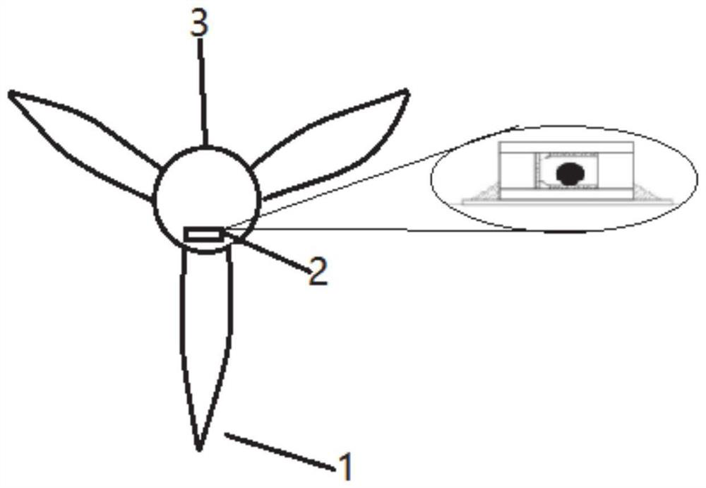
[0026] In the technical solutions disclosed in one or more embodiments, such as figure 1 As shown, the measuring device for the azimuth and rotational speed of the fan wheel based on the ball switch includes a ball switch and a signal processing terminal, and the signal processing terminal is connected to the ball switch in communication; the ball switch is arranged on the fan blade 1 corresponding to the fan Location.

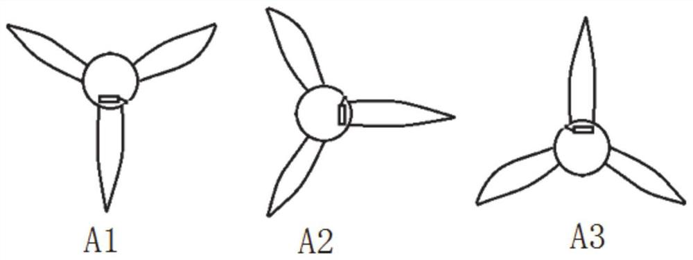
[0027] In this embodiment, the ball switch is set at the position corresponding to the fan blade, so that the system can identify the azimuth angle of the current fan blade, and realize accurate measurement of the azimuth angle of the fan rotor.

[0028] In a further technical solution, the ball switch is arranged at a position corresponding to the fan blade 1 of the fan. Optionally, it can be arranged on the fan hub 3 or on the fan blade 1 , specifically: the ball switch is arranged in the fan hub directly opposite to the fan blade 1 or at the root of the fa...

Embodiment 2

[0037] Based on the device in Embodiment 1, this embodiment provides a method for measuring the azimuth and rotational speed of the fan rotor based on the ball switch. The method can be implemented in a signal processing terminal, including the following steps:

[0038] Step 1. Obtain the electrical signal output by the ball switch;

[0039] Step 2. Obtain the rotational speed of the wind rotor according to the change cycle data of the electrical signal;

[0040] Step 3. Determine the current azimuth angle of the wind rotor according to the electrical signal value and the initial azimuth angle of the blades of the wind rotor.

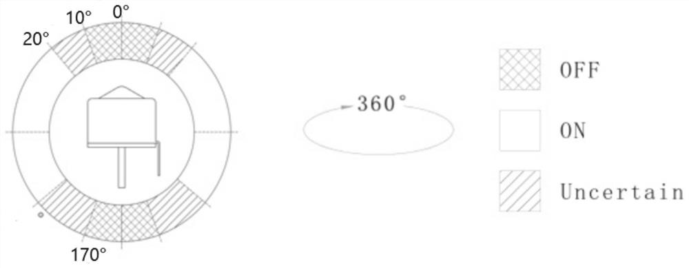
[0041] In this embodiment, the azimuth angle of the blade is determined by collecting the level signal of the ball switch, which is determined by the setting method of the ball switch. The angle perpendicular to the fan blade 1 is set, so that the corresponding designated signal can be output in the vertical position. The interval between two low-level...

Embodiment 3

[0047] Based on Embodiment 1 and Embodiment 2, this embodiment proposes a control system for wind power generators. The system is provided with the measuring device for the azimuth and rotational speed of the fan rotor based on the ball switch in Embodiment 1, and adopts the method described in Embodiment 2. The method for measuring the azimuth and rotational speed of the fan rotor based on the ball switch described above controls the generator set according to the measured rotational speed, and realizes the pitch control according to the measured azimuth angle of the wind rotor.


PUM


Abstract

The invention provides a device and method for measuring the azimuth angle and the rotating speed of a wind wheel of a wind turbine based on a ball switch. The device comprises the ball switch and a signal processing terminal which is in communication connection with the ball switch. The ball switch is arranged at a position corresponding to a wind turbine blade of the wind turbine. By arranging the ball switch in a hub of a wind generating set, the attitude angle and the angular velocity of the wind wheel of the wind turbine are accurately measured, the structure is simple, implementation is easy, the measurement precision is high, and the use requirements of high-power and offshore units can be met. Effective, timely and stable detection of the azimuth angle of the wind wheel of the wind turbine can be achieved, independent variable pitch control can be achieved, the purpose of reducing the fatigue load of a unit can be achieved, and the service life of the unit is prolonged.

Description

technical field [0001] The present disclosure relates to the technical field related to wind power generation, and in particular, relates to a measuring device and method for the azimuth and rotational speed of a fan rotor based on a ball switch. Background technique [0002] The statements in this section merely provide background information related to the present disclosure and may not necessarily constitute prior art. [0003] The speed monitoring of the wind rotor (or impeller) of the wind turbine is very important. If the speed of the wind rotor is too high, it will cause serious accidents such as speeding and tower collapse of the wind turbine. Calculate the speed of the wind rotor by detecting the angular velocity of the blades. When the speed exceeds the set threshold, the blades can be retracted in time to realize aerodynamic braking, thereby protecting the safety of the unit. [0004] The inventors found that the existing method for detecting the speed of the win...

Claims


Application Information

Patent Timeline
Patent Type & Authority Applications(China)
IPC IPC(8): F03D17/00F03D80/00F03D7/02
CPCF03D17/00F03D80/00F03D7/0236Y02E10/72
Inventor 王伟狄振锋刘茸茸苗云涛
Owner CRRC WIND POWER(SHANDONG) CO LTD
Why Eureka
Try Eureka