Webbing take-up device

一种卷绕装置、安全带的技术,应用在车内安全带、皮带收紧器、运输和包装等方向,能够解决配合余量增大、爪部难以通过窗部、组装性变差等问题,达到增大对置面积的效果

Active Publication Date: 2014-07-23
KK TOKAI RIKA DENKI SEISAKUSHO
View PDF6 Cites 8 Cited by
  • Summary
  • Abstract
  • Description
  • Claims
  • Application Information

AI Technical Summary

Problems solved by technology

However, if the fitting margin between the claw portion of the elastic claw piece and the support body is increased, it will be difficult for the claw portion to pass through the window portion, thereby degrading the assembly property.

Method used


Image

  • Webbing take-up device
  • Webbing take-up device
  • Webbing take-up device

Examples


Embodiment Construction

[0028] (Structure of this embodiment)

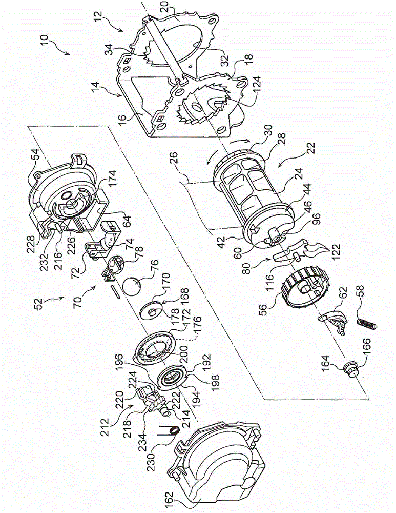
[0029] figure 1 The outline of the whole structure of the seat belt retractor 10 which concerns on one Embodiment of this invention is shown using an exploded perspective view in .

[0030] The device body 12 of the seat belt take-up device 10 includes a frame 14 . The frame 14 includes a plate-shaped back plate 16 . Extend and protrude from one end of the width direction of the backboard 16 to one side of the thickness direction of the backboard 16, and protrude from the other end of the width direction of the backboard 16 to one side of the thickness direction of the backboard 16 (that is, with the footboard 18 from the side of the backboard 16 The same direction as the direction in which the extension protrudes) extends and protrudes with a foot plate 20 . Therefore, the frame 14 is formed in a concave shape as a whole, and the back plate 16 of the frame 14 is directly or indirectly fixed to a frame member, a reinforcement member, ...


PUM


Abstract

The present invention provides a webbing take-up device that can enlarge an area in which a support body and an engagement portion face one another without impairing the attachability of a switch member to the support body. In the webbing take-up device (10), an open portion (242) is formed in the other side, in a direction about a rotational axis of a switch pawl (212), of a sensor holder (54). In a state where an engagement piece (224) is positioned on the outside of the open portion (242), the switch pawl is rotated about a shaft (216) to cause the engagement piece (224) to enter in a window portion (226), so, a distal end of the engagement piece, bent in a hook shape, faces to a regulation wall in an axial direction of the shaft (216). It is not necessary to elastically deform the engagement piece when bringing the regulation wall and the engagement piece into facing. Therefore, the engagement allowance in the engagement piece with the regulation wall can be enlarged and the distal end of the engagement piece can be prevented from crossing over the regulation wall and moving toward the shaft side.

Description

technical field [0001] The present invention relates to a seat belt take-up device constituting a seat belt device of a vehicle. Background technique [0002] In the seat belt take-up device disclosed in Patent Document 1 below (referred to as a seat belt retractor in Patent Document 1), when a predetermined amount of seat belt is pulled out, the link rotates in conjunction with this, thereby restricting the seat belt retractor. Rotation of the control panel. If the seat belt is further pulled out in this state, relative rotation occurs between the reel (referred to as a bobbin in Patent Document 1), more specifically, the winding shaft, and the control plate, and the lock arm and the relative rotation Engages with the latch plate of the winding shaft so as to rotate interlockingly. Thereby, rotation of the winding shaft, and more specifically, the spool in the pulling-out direction is restricted, thereby restricting the pulling-out of the seat belt from the spool. [000...

Claims


Application Information

Patent Timeline
Patent Type & Authority Applications(China)
IPC IPC(8): B60R22/34
CPCB60R22/3416B60R22/36
Inventor 山田和弘角屋敷晃
Owner KK TOKAI RIKA DENKI SEISAKUSHO
Why Eureka
Try Eureka