Combined electrode and three-level high power module thereof

A combined, three-level technology, which is applied to output power conversion devices, AC power input conversion to DC power output, circuits, etc., can solve the problems of power module stray inductance, large loss, and large current loop area. Achieve the effects of reducing stray inductance and loss, improving safety, and improving dynamic and static current sharing performance

Active Publication Date: 2016-07-20
YANGZHOU GUOYANG ELECTRONICS CO LTD
View PDF7 Cites 2 Cited by
  • Summary
  • Abstract
  • Description
  • Claims
  • Application Information

AI Technical Summary

Problems solved by technology

[0003] In the power module in the prior art, the positive electrode main body and the intermediate electrode main body or the negative electrode main body and the intermediate electrode main body are often arranged alternately in parallel, and the positive electrode connection part is connected to the intermediate electrode connection part or the negative electrode connection part is connected to the intermediate electrode. The parts are not directly opposite and parallel, and the positive electrode and the middle electrode or the negative electrode and the middle electrode have a small facing area, resulting in a large current loop area between the positive electrode and the middle electrode or the negative electrode and the middle electrode, so that the power module Larger stray inductance and losses

Method used


Image

  • Combined electrode and three-level high power module thereof
  • Combined electrode and three-level high power module thereof
  • Combined electrode and three-level high power module thereof

Examples


Embodiment 1

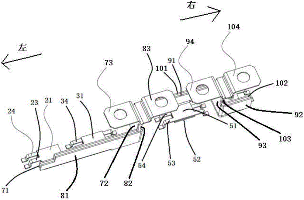
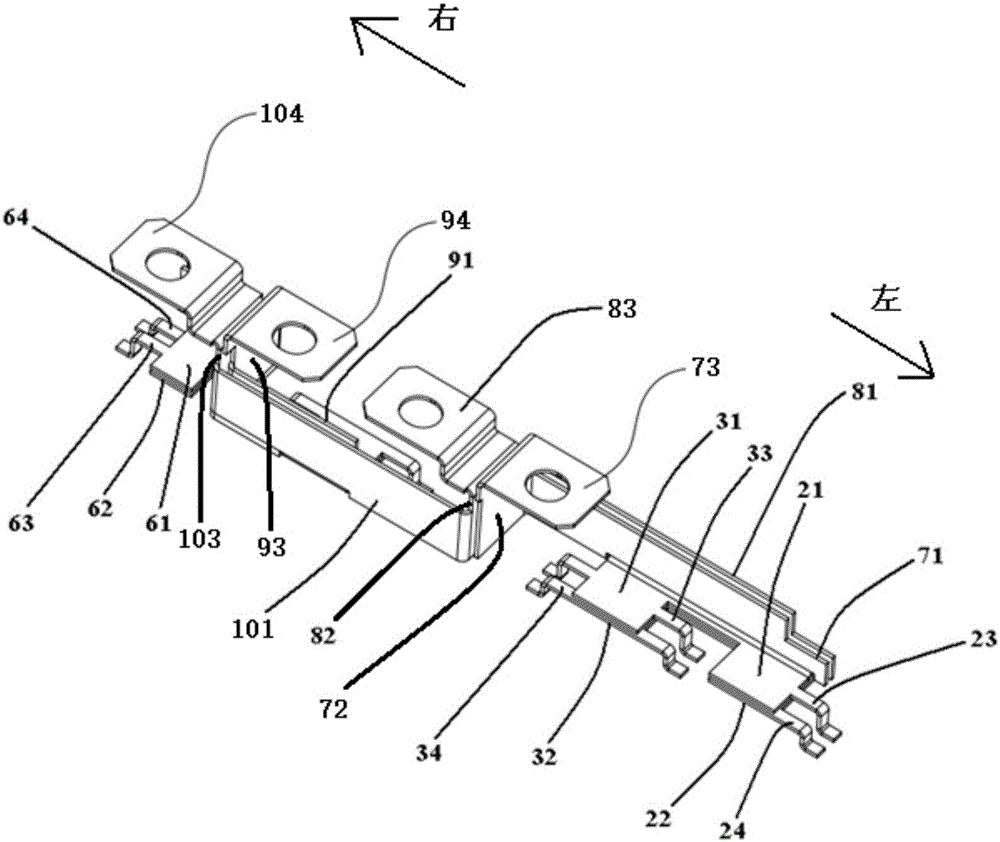
[0041] Such as figure 1 , figure 2 As shown, the combined electrode includes a negative electrode, a first intermediate electrode, a positive electrode and a second intermediate electrode. The negative electrode includes a negative electrode connection part 72 , the side end of the negative electrode connection part 72 extends to the left at 90° from the negative electrode body part 71 , and the top of the negative electrode connection part 72 bends to the left to form a negative electrode lead-out part 73 . The first intermediate electrode includes a first intermediate electrode connecting portion 82, one side end of the first intermediate electrode connecting portion 82 extends to the left at 90° from the first intermediate electrode main body portion 81, and the top of the first intermediate electrode connecting portion 82 bends to the right Fold out the first intermediate electrode lead-out portion 83 . The positive electrode includes a positive electrode connecting por...

Embodiment 2

[0045] Such as figure 1 , figure 2 As shown, the combined electrode includes a negative electrode, a first intermediate electrode, a positive electrode and a second intermediate electrode. The negative electrode includes a negative electrode connection part 72 , the side end of the negative electrode connection part 72 extends to the left at 90° from the negative electrode body part 71 , and the top of the negative electrode connection part 72 bends to the left to form a negative electrode lead-out part 73 . The first intermediate electrode includes a first intermediate electrode connecting portion 82, the side end of the first intermediate electrode connecting portion 82 extends to the left at 90° from the first intermediate electrode main body portion 81, and the top of the first intermediate electrode connecting portion 82 bends to the right. The first intermediate electrode lead-out portion 83 . The positive electrode includes a positive electrode connecting portion 93,...

Embodiment 3

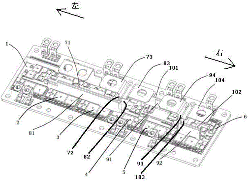
[0050] Such as image 3 As shown, the power module includes six insulating substrates arranged in a row, of which the three insulating substrates on the left are the lower half-bridge insulating substrates, which are respectively the first lower half-bridge insulating substrate 1, the second lower half-bridge insulating substrate 2 and the third lower half-bridge insulating substrate The lower half-bridge insulating substrate 3 and the three insulating substrates on the right are the upper half-bridge insulating substrates, which are respectively the first upper half-bridge insulating substrate 4 , the second upper half-bridge insulating substrate 5 and the third upper half-bridge insulating substrate 6 .

[0051] Such as Figure 4 As shown, the first lower half-bridge insulating substrate 1, the second lower half-bridge insulating substrate 2, the third lower half-bridge insulating substrate 3, the first upper half-bridge insulating substrate 4, the second upper half-bridge i...


PUM


Abstract

The invention discloses a combined electrode. The electrode comprises a negative electrode, a first intermediate electrode, a positive electrode and a second intermediate electrode, wherein a negative electrode main body portion and a first intermediate electrode main body portion, a negative electrode connecting portion and a first intermediate electrode connection portion are arranged in parallel and in a direct facing mode, and a positive electrode main body portion and a second intermediate electrode main body portion, a positive electrode connecting portion and a second intermediate electrode connection portion are arranged in parallel and in the direct facing mode so that direct facing areas between the negative electrode and the first intermediate electrode, and between the positive electrode and the second intermediate electrode are increased, current loop areas between the negative electrode and the first intermediate electrode, and between the positive electrode and the second intermediate electrode are reduced and a stray inductance and losses of the combined electrode are effectively reduced. The invention also discloses a three-level high power module adopting the combined electrode. A stray inductance and losses of the power module are effectively reduced.

Description

technical field [0001] The invention relates to the field of power electronics, in particular to a combined electrode and a three-level high-power module thereof. Background technique [0002] The power module is a power switch module packaged by power electronic devices such as metal oxide semiconductors (power MOS tubes), insulated gate field effect transistors (IGBTs), and fast recovery diodes (FRDs) according to certain functions. Power conversion in various occasions such as automobiles, photovoltaic power generation, wind power generation, and industrial frequency conversion. [0003] In the power module in the prior art, the positive electrode main body and the intermediate electrode main body or the negative electrode main body and the intermediate electrode main body are often arranged alternately in parallel, and the positive electrode connection part is connected to the intermediate electrode connection part or the negative electrode connection part is connected t...

Claims


Application Information

Patent Timeline
Patent Type & Authority Applications(China)
IPC IPC(8): H01L23/48H01L25/07
CPCH01L23/48H01L25/07H01L25/072H02M7/003H02M7/487H01L25/18H01L23/645H01L23/50
Inventor 徐文辉王玉林滕鹤松
Owner YANGZHOU GUOYANG ELECTRONICS CO LTD
Why Eureka
Try Eureka