Armature for linear motor

A technology of linear motors and armatures, applied in the direction of electric components, electromechanical devices, electrical components, etc., can solve the problems of large pressure loss of refrigerant, large deviation of the overall temperature distribution of the armature, and long cooling pipelines, etc., to achieve reduction Effects of temperature gradient, improvement of cooling effect, and increase of facing area

Inactive Publication Date: 2012-02-01
SANYO DENKI CO LTD
View PDF4 Cites 2 Cited by
  • Summary
  • Abstract
  • Description
  • Claims
  • Application Information

AI Technical Summary

Problems solved by technology

[0004] However, in conventional armatures for linear motors, there is a problem that the pressure loss of the refrigerant is large due to the long cooling lines.
In addition, there is a problem that the temperature gradient of the refrigerant in the cooling pipe increases, resulting in a large deviation in the temperature distribution of the entire armature.

Method used


Image

  • Armature for linear motor
  • Armature for linear motor
  • Armature for linear motor

Examples


Embodiment Construction

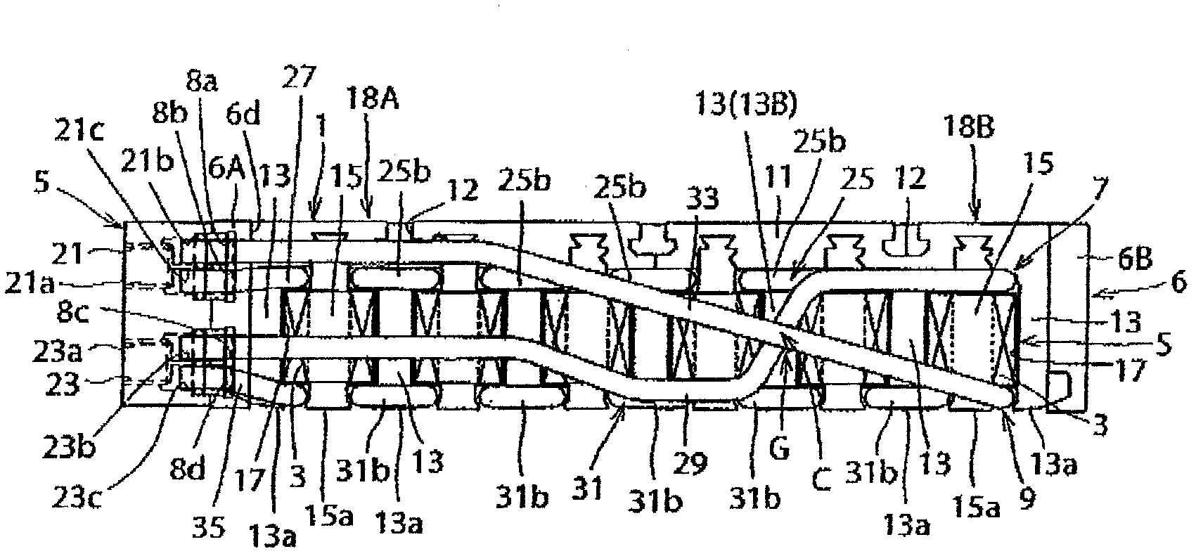
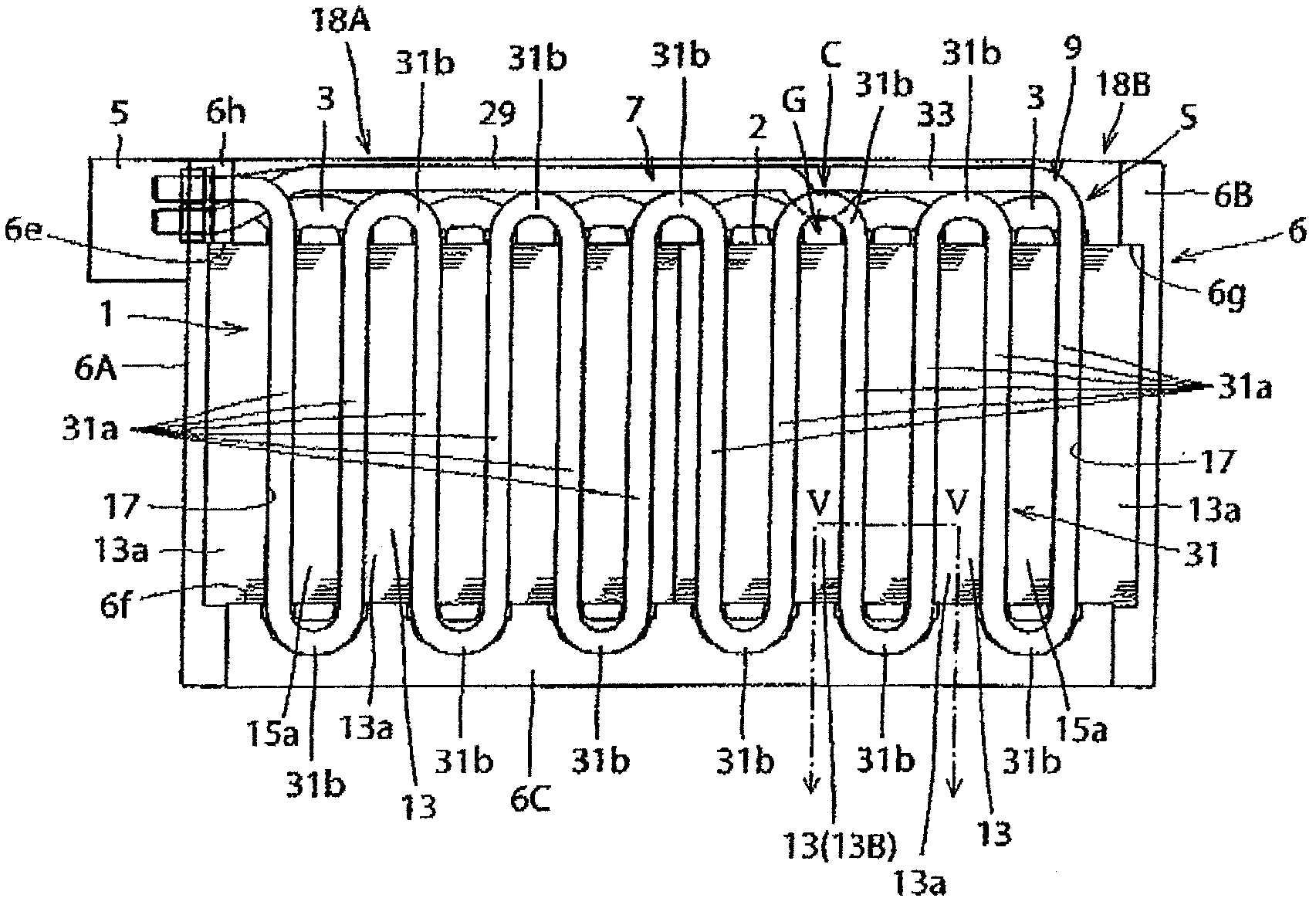
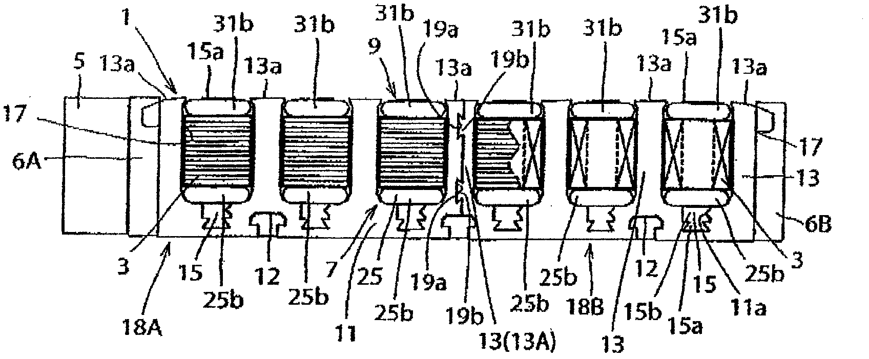
[0023] Hereinafter, an embodiment of the present invention will be described in detail with reference to the drawings. Figure 1 ~ Figure 4 It is a front view, a top view, a back view, and a left side view of the armature for linear motors which concerns on one Embodiment of this invention. As shown in each figure, the armature for a linear motor of this example constitutes the mover of the linear motor, and has an armature core 1, six field windings 3, a manifold main body 5, and first and second cooling lines 7, 9. The armature core 1 has a yoke 11 and thirteen pole teeth 13 , 15 . Yoke 11 facing figure 1 The paper surface extends in a straight line in the left-right direction (lengthwise direction). The thirteen pole teeth 13 and 15 are arranged along the longitudinal direction of the yoke 11 (the moving direction of the mover of the linear motor). The thirteen pole teeth are arranged at intervals in the longitudinal direction, and a slot 17 is formed between two adjacen...


PUM


Abstract

A linear motor armature in which pressure loss of a coolant flowing in a cooling conduit and possible significant non-uniformity in temperature distribution are reduced over the entire armature. A manifold 5, 6h and a pair of cooling conduits 7, 9 are configured such that a coolant is supplied from one connecting conduit 27 of the cooling conduit 7, and one connecting conduit 33 of the cooling conduit 9, and discharged from the other connecting conduit 29 of the cooling conduit 7 and the other connecting conduit 35 of the cooling conduit 9.

Description

technical field [0001] The present invention relates to an armature for a linear motor. Background technique [0002] In Japanese Patent Application Laid-Open No. 2008-35698, an armature for a linear motor is disclosed, which includes: a yoke extending linearly, and a plurality of yokes arranged along the longitudinal direction of the yoke and fixed to the yoke. An armature core composed of pole teeth; a plurality of field windings that excite a plurality of pole teeth. In this armature for a linear motor, in order to cool the heat generated from the plurality of field windings, the refrigerant is placed in the slots between two adjacent pole teeth so that a part of the field windings are sandwiched therebetween. Internally flowing cooling lines. This cooling line is used by bending a tube into a zigzag shape. [0003] Patent Document 1: Japanese Patent Laid-Open No. 2008-35698 [0004] However, the conventional armature for a linear motor has a problem in that the press...

Claims


Application Information

Patent Timeline
Patent Type & Authority Applications(China)
IPC IPC(8): H02K41/02H02K41/03
CPCH02K3/24H02K9/19H02K41/03H02K9/197H02K9/22H02K9/193
Inventor 杉田聪三泽康司
Owner SANYO DENKI CO LTD
Why Eureka
Try Eureka