Vibrative charging tank with liner plate

A feeding trough and liner technology, applied in vibrating conveyors, conveyors, transportation and packaging, etc., can solve the problems of easy loosening of liner and liner joints, loose liner and liner joints, equipment failure and maintenance Increase and other problems, to achieve the effect of simple and reliable connection structure, stable operation, and small maintenance workload

Active Publication Date: 2014-07-23
CISDI ENG CO LTD
View PDF5 Cites 2 Cited by
  • Summary
  • Abstract
  • Description
  • Claims
  • Application Information

AI Technical Summary

Problems solved by technology

[0002] In the prior art, it is a conventional idea to install a liner on the vibrating feeding tank to improve the life and maintainability of the feeding tank. However, due to the vibration of the feeding tank, the lining board and the connecting parts of the lining board are very easy to loosen, resulting in the use of The increase of process abnormal noise and mechanical harmful impact, the increase of equipment failure and maintenance, and the looseness of liner and liner connection have become a difficult problem for vibration feeding equipment, so the installation of liner and trough to work reliably under vibration is satisfied. The structure is the key technology for the success of the feeding chute with liner

Method used


Image

  • Vibrative charging tank with liner plate
  • Vibrative charging tank with liner plate
  • Vibrative charging tank with liner plate

Examples


Embodiment Construction

[0018] The present invention will be further described below in conjunction with the accompanying drawings and embodiments.

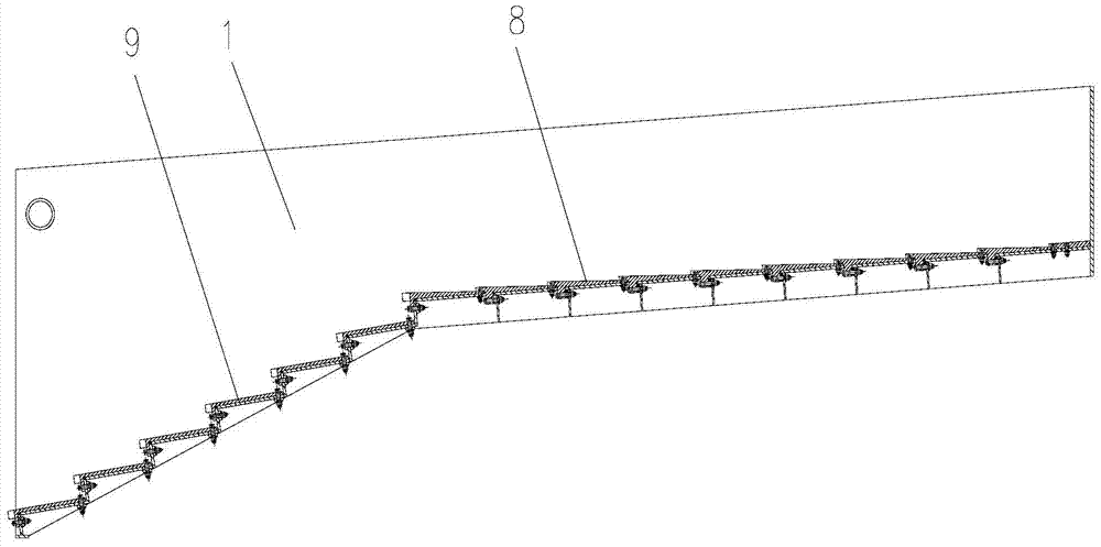
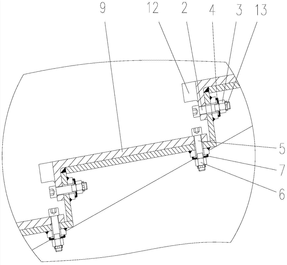
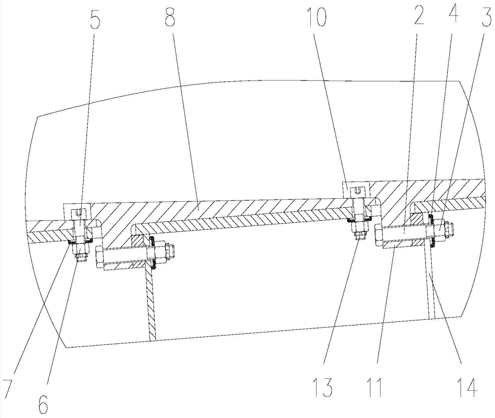
[0019] As shown in the figure, the vibrating feeding tank with liners in this embodiment includes a tank body 1 and several tank bottom liners. The head of the tank bottom liner is fixedly connected to the bottom of the tank body through a horizontally arranged bolt assembly. The tail of the liner at the bottom of the tank is fixedly connected to the bottom of the tank body through a vertically arranged bolt assembly;

[0020] The horizontally arranged bolt assembly includes a horizontal bolt 2, a nut 3 and a spring washer 4 that cooperate with the horizontal bolt, and the vertically arranged bolt assembly includes a vertical bolt 5, a nut 6 that cooperates with the vertical bolt, and a spring washer 7 .

[0021] In the vibrating feeding trough with a lining plate in this embodiment, the trough body 1 performs horizontal reciprocating vibration during ...


PUM


Abstract

The invention discloses a vibrative charging tank with a liner plate. The vibrative charging tank comprises a tank body and the tank bottom liner plate, wherein the head portion of the tank bottom liner plate is fixedly connected with the tank body bottom through a transversely-arranged bolt assembly, the tail portion of the tank bottom liner plate is fixedly connected with the tank body bottom through a vertically-arranged bolt assembly. When the charging tank works, the tank body performs horizontal reciprocating vibration, the transversely-arranged bolt assembly provides a horizontal fastening force for the tank bottom liner plate and accordingly can effectively resist horizontal vibration inertia force and horizontal friction force enabling the liner plate to be loosened, and the vertically-arranged bolt assembly provides vertical fastening force for the tank bottom liner plate and accordingly can effectively resist vertical inertia force enabling the liner plate to be loosened. In addition, pre-compression amount of a spring gasket can automatically compensate a gap produced between a nut and an elastic gasket when the liner plate vibrates, and nut loosening can be avoided. Therefore, the vibrative charging tank has the advantages that the liner plate and the tank bottom are tightly connected, the liner plate is not loosened when working for a long period of time, and the charging tank is stable in running, small in maintenance work amount, long in service life and the like.

Description

technical field [0001] The invention relates to a feeding device, in particular to a vibrating feeding tank with a liner. Background technique [0002] In the prior art, it is a conventional idea to install a liner on the vibrating feeding tank to improve the life and maintainability of the feeding tank. However, due to the vibration of the feeding tank, the lining board and the connecting parts of the lining board are very easy to loosen, resulting in the use of The increase of process abnormal noise and mechanical harmful impact, the increase of equipment failure and maintenance, and the looseness of liner and liner connection have become a difficult problem for vibration feeding equipment, so the installation of liner and trough to work reliably under vibration is satisfied. The structure is the key technology for the success of the feeding chute with liner. Contents of the invention [0003] In view of this, the object of the present invention is to provide a vibratin...

Claims


Application Information

Patent Timeline
Patent Type & Authority Applications(China)
IPC IPC(8): B65G27/08
Inventor 黄其明谈存真施维枝高瞻
Owner CISDI ENG CO LTD
Why Eureka
Try Eureka