a mechanical lock

A mechanical lock and lock hook technology, applied in the field of mechanical locks, can solve the problems of complex structure and large occupied volume of locks, and achieve the effect of small occupied volume and convenient operation.

Inactive Publication Date: 2017-01-04
YIFENG MFG
View PDF8 Cites 0 Cited by
  • Summary
  • Abstract
  • Description
  • Claims
  • Application Information

AI Technical Summary

Problems solved by technology

[0003] In order to overcome the disadvantages of complex structure and large occupied volume in the prior art, the present invention provides a lock which is easy to operate and occupies a small area

Method used


Image

  • a mechanical lock
  • a mechanical lock
  • a mechanical lock

Examples


Embodiment

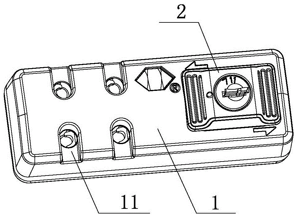
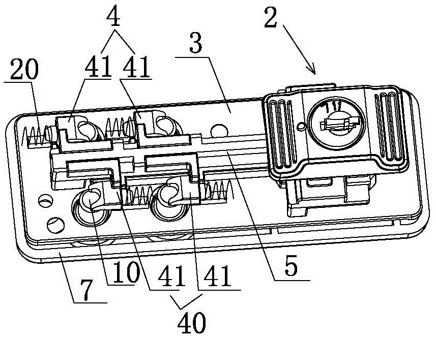
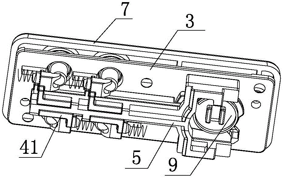
[0032] Example: see Figure 1 to Figure 8 .

[0033] A mechanical lock, comprising a base plate 3 and a face shell 1 fixedly connected, an accommodation space is formed between the base plate 3 and the face shell 1, two groups of lock hook assemblies are arranged on the left side of the accommodation space, and there are also two sets of locking hook assemblies in the accommodation space. On the elastic member 20 reset by the locking hook assembly, the opening directions of the two sets of locking hook assemblies are opposite. The right side of the accommodation space is provided with a locking device, and the locking device can move left and right relative to the bottom plate 3. The right side of the upper side is provided with a through hole, and the control end of the locking device stretches out of the through hole; the locking device is linked with the front locking hook assembly 4 and the rear locking hook assembly 40 respectively; when the locking device is unlocked, th...


PUM


Abstract

The invention relates to a mechanical lock. The mechanical lock comprises a base plat and a face shell, wherein the base plate and the face shell are fixedly connected, a containing space is formed between the base plate and the face shell, two lock hook assemblies are arranged on the left side of the containing space, elastic parts are further arranged in the containing space, the two lock hook assemblies are opposite in unlocking direction, a locking device is arranged on the right side of the containing space, and can move left and right relative to the base plate, a through hole is formed in the right side of the face shell, an operating end of the locking device extends out of the through hole, and the locking device is in linkage connection with the front lock hook assembly and the rear lock hook assembly. After the locking device is unlocked, when the locking device moves towards the left, one of the lock hook assemblies is unlocked; when the locking device moves towards the right, the other lock hook assembly is unlocked, and one of the lock hook assemblies resets under the action of the elastic parts. According to the mechanical lock, due to the fact that the two lock hook assemblies which are opposite in locking direction and a control rod are arranged, the lock hook assemblies of the mechanical lock can be respectively unlocked, occupied space is small, and operation is convenient.

Description

technical field [0001] The invention belongs to the technical field of mechanical locks, and in particular relates to a mechanical lock. Background technique [0002] With the development of society, the number of times people go out to travel gradually increases, and more and more items are carried on trips. In order to facilitate carrying, many people use larger bags. Both layers use zippers as switch connectors. In order to centrally manage multiple zippers, bags generally use a lock with a zipper hole; Both sides of the lock; for the convenience of management, the upper and lower zippers are divided into two parts, the zipper located above the lock is locked on the upper side of the lock, and the zipper located below the lock is locked on the lower side of the lock; such as the Chinese patent application number 201320307959.0, The name is: a kind of lock, which controls the upper lock hook group and the lower lock hook group respectively through the left and right butto...

Claims


Application Information

Patent Timeline
IPC IPC(8): E05B65/52
Inventor 赖秀兴
Owner YIFENG MFG
Why Eureka
Try Eureka