Multi-joint self-expansion anchor rod

A bolt and self-expanding technology, which is used in the installation of bolts, mining equipment, earthwork drilling and mining, etc., can solve the problems of failure to fully exert the mechanical function of the bolt body, the impact of tunnel engineering quality and progress, the strength of the rod body material and the section Require advanced issues, achieve high social and economic value, good support effect, simple and fast construction process

Inactive Publication Date: 2014-07-23
罗宗帆
View PDF6 Cites 8 Cited by
  • Summary
  • Abstract
  • Description
  • Claims
  • Application Information

AI Technical Summary

Problems solved by technology

The problem of anchoring at the end is: due to the large axial force of the anchor rod, the requirements for the strength and section of the rod body material are high, so the mechanical effect of the anchor rod body cannot be fully exerted.
The full-length bonded anchorage is mostly related to the fullness of the grouting and the friction force generated by the strength of the grout material after the grout is solidified. However, it is often difficult to control the diffusion of the grout to the voids of the rock (soil) body during the grouting process, resulting in blockage. In addition, the construction technology requirements of anchor grouting are high and the construction is difficult, which also affects the anchoring effect of the anchor to a considerable extent and even affects the construction progress. Moreover, the construction period of the full-length bonded anchor is long, which affects the entire tunnel. The engineering quality and progress of the project have a greater impact

Method used


Image

  • Multi-joint self-expansion anchor rod
  • Multi-joint self-expansion anchor rod
  • Multi-joint self-expansion anchor rod

Examples


Embodiment Construction

[0019] The content of the present invention will be further described below in conjunction with the accompanying drawings, but the actual application form of the present invention is not limited to the illustrated embodiment.

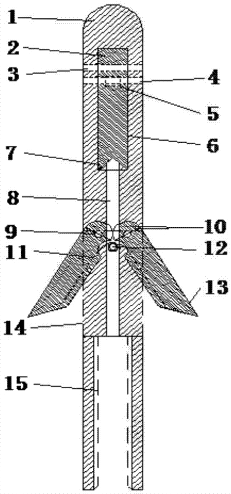
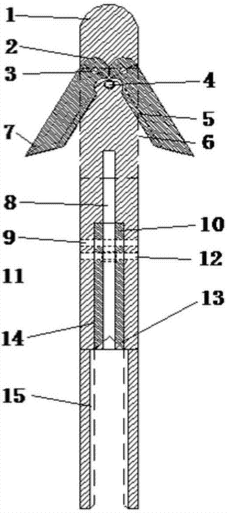
[0020] Referring to the accompanying drawings, the multi-section head self-expanding anchor rod of the present invention includes a long rod-shaped anchor head 1 and one or more segments of the anchor rod body 30 matched with the anchor head 1 .

[0021] The structure of the anchor head 1 is as follows figure 1 and figure 2 shown. A bar-shaped square hole 6, 14, which is orthogonal in spatial position, is provided at the head and the middle of the anchoring head rod body, and a group of elastic self-expanding wedges are respectively installed in the two bar-shaped square holes 6, 14. Among them, the elastic self-expanding wedge installed at the head position includes an inverted V-shaped spring 5 fixed on the anchor head rod body through a spring fix...


PUM


Abstract

The invention relates to a multi-joint self-expansion anchor rod for tunnel engineering construction. The multi-joint self-expansion anchor rod comprises an anchoring head and one or more anchor rod bodies, strip-shaped square holes orthogonal in space position are respectively formed in the head portions and the middle portions of the anchoring head and the anchor rod bodies, a group of elastic self-expansion wedge blocks are respectively installed in the strip-shaped square holes through pins and comprises an inverted V-shaped spring and two wedge blocks symmetrically attached to the outer edge of a spring reed. In the actual construction, the wedge blocks attached to the outer edge of the spring reed are always open and tightly in contact with a surrounding rock in the anchor rod feeding process, and after the anchor rods are fed to the bottom, the anchor rods are embedded into a pore wall rock to play an anchoring effect of the anchor rods. After anchoring is finished, reinforcement can be achieved through grouting holes or the designed anchoring effect can be achieved without the anchor rod grouting construction process. The multi-joint self-expansion anchor rod for tunnel engineering construction is reasonable in structure, convenient to construct, quick, high in efficiency, good in anchoring strength and supporting effect and capable of keeping the integrity and stability of the surrounding rock to the most extent.

Description

technical field [0001] The invention belongs to the technical field of rock (soil) engineering construction equipment, and relates to a self-expanding bolt with multiple joints for tunnel engineering construction. Background technique [0002] Bolt anchoring is a reinforcement method in which the structure and the formation are tightly linked together through the bolt in the formation. During work, the shear strength of the anchor and the surrounding formation is relied on to transmit the tensile force of the structure, so that the formation itself is reinforced. To achieve the purpose of maintaining the stability of structures and rock masses. [0003] At present, in tunnel engineering construction, there are mainly two types of bolt anchorage: end anchorage and full-length bonded anchorage. The problem of anchoring at the end is: due to the large axial force of the anchor rod, the requirements for the strength and section of the rod body material are high, so the mechanic...

Claims


Application Information

Patent Timeline
Patent Type & Authority Applications(China)
IPC IPC(8): E21D21/00
Inventor 罗宗帆王梦恕谭忠盛张卿
Owner 罗宗帆
Why Eureka
Try Eureka