

Method for side air supply of driving face of large-diameter deep vertical shaft
A large-diameter, vertical shaft technology, applied in mine/tunnel ventilation, earthwork drilling, mining equipment, etc., can solve problems such as the inability to effectively improve the working environment of the driving face, the restriction of conventional ventilation and dust removal functions, and the restriction of the construction of large-scale deep mines, etc. Achieving wide availability, reduced air age, improved thermal environment
- Summary
- Abstract
- Description
- Claims
- Application Information
AI Technical Summary
Problems solved by technology
Method used
Image

Examples
Embodiment Construction
[0017] An embodiment of the present invention will be further described below in conjunction with accompanying drawing:
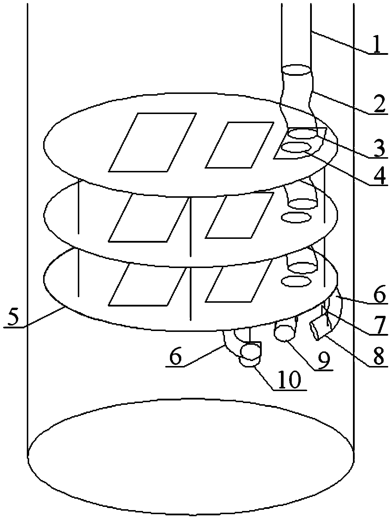
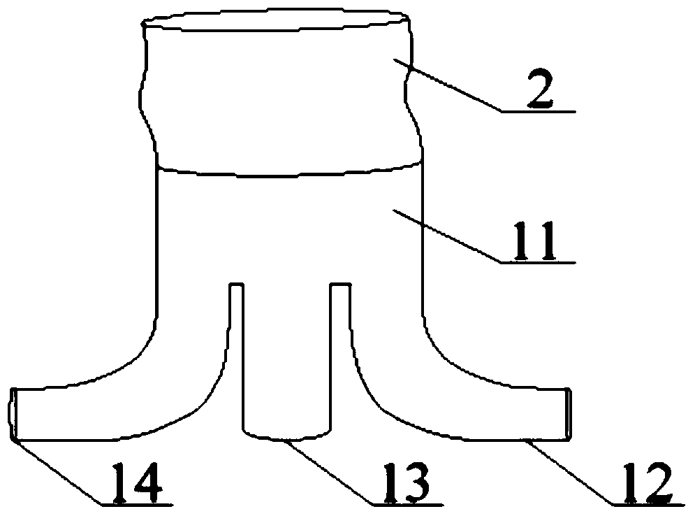
[0018] The method for supplying air to the side of the excavation face of a large-diameter deep shaft of the present invention includes setting an air supply cylinder passing through one side of the multi-layer suspension plate in the vertical shaft, and the air supply cylinder includes a main air supply cylinder 1 and a vertical flexible air cylinder 2 sequentially connected , Vertical flexible air duct hole 3. As the excavation depth of the vertical shaft continues to increase, the ambient temperature of the excavation surface gradually increases. Firstly, the three induction tuyere pipes 8, 9, and 10 are respectively fixed to the bottom of the suspension plate 5 on the last layer through the bracket 7 near the main air supply tube hole 4 to induce The air outlet pipes 8, 9, 10 are detachable and adjustable in angle, and can realize air supply in differen...
PUM
 Abstract
Description
Claims
Application Information