Double-lever type power energy-saving device

An energy-saving device and double-lever technology, which is applied in the direction of transmission, belt/chain/gear, mechanical equipment, etc., can solve the problems of high consumption of non-renewable energy, low utilization rate of power and power, and increased mechanical operation cost, and achieves a simple structure. , The effect of high mechanical transmission efficiency and power saving

Inactive Publication Date: 2014-07-23
郭富强
View PDF0 Cites 3 Cited by
  • Summary
  • Abstract
  • Description
  • Claims
  • Application Information

AI Technical Summary

Problems solved by technology

[0002] At present, there are diesel engines, gasoline engines, and electric motors that provide power for various working machines. When driving power, a large amount of diesel, gasoline, or electric energy is required to be burned, and the prices of diesel, gasoline, and electricity are constantly rising. The operating cost is greatly increased, and the exhaust gas discharged from the fuel will pollute the environment
Secondly, diesel engines, gasoline engines, electric motors, etc. are all directly driven by power machinery. Their function is to directly transmit power to the working machine, but the power loss is relatively large during the process of transmitting power to the working machine, which leads to power loss. The current status of power utilization is extremely low, and the operation of various power machinery consumes a lot of non-renewable energy, which leads to the large energy consumption of the existing power output and is not energy-saving.

Method used


Image

  • Double-lever type power energy-saving device
  • Double-lever type power energy-saving device
  • Double-lever type power energy-saving device

Examples


Embodiment Construction

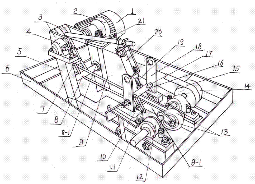
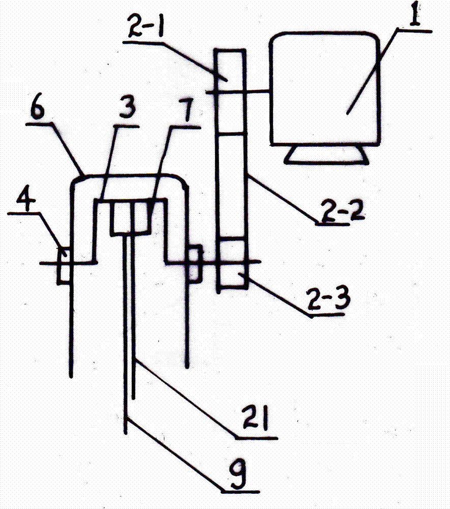
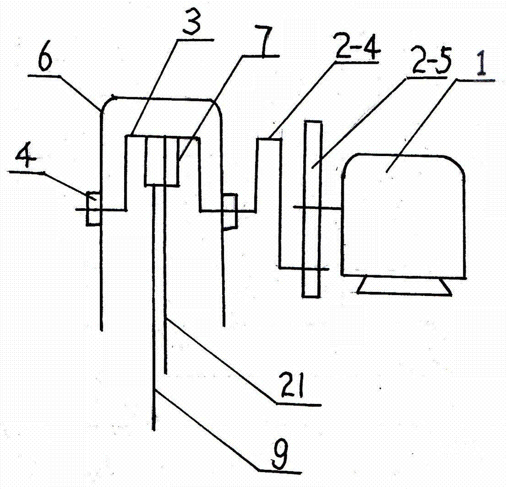
[0021] figure 1 The labels are: power machine 1, transmission part 2, driving crankshaft 3, front bearing seat 4, groove bracket 5, base 6, connecting piece 7, roller shaft 8, roller 8-1, power lever 9, double plate 9 -1. Lever fulcrum shaft 10, fork rod 11, rear bearing seat 12, driven crankshaft 13, pulley 14, belt 15, shift fork 16, shift fork fixed shaft 17, shift fork bracket 18, connecting screw 19, shift fork pull rod 20 , Crankshaft connecting rod 21.

[0022] see figure 1 , figure 2 , the double-lever power energy-saving device of the present invention comprises a power machine 1 and a double-lever power transmission mechanism, wherein the power machine 1 is a diesel engine or a gasoline engine or an electric motor, and the double-lever power transmission mechanism is composed of a base 6, a transmission member 2, a driving crankshaft 3, Front bearing seat 4, grooved support 5, roller shaft assembly, crankshaft connecting rod 21, power lever 9, shift fork assembly...


PUM


Abstract

The invention relates to a double-lever type power energy-saving device which comprises a power machine and a double-lever power transmission mechanism. The mechanism is composed of a base, a transmission piece, a driving crank, front bearing seats, groove-type supports, idler wheel shaft assemblies, a crank connecting rod, power levers, a shift fork assembly, a rear bearing seat and a driven crank. The tops of the groove-type supports are provided with the front bearing seats respectively. The driving crank is arranged between the two front bearing seats and connected with the power machine through the transmission piece. The idler wheel shaft assemblies capable of moving vertically along grooves are arranged in the groove-type supports. One end of the crank connecting rod is hinged to the driving crank and the other end of the crank connecting rod is hinged to the shift fork assembly. The front ends of the power levers are connected with the driving crank through connecting pieces and the rear ends of the power levers are connected with the driven crank. According to the double-lever type power energy-saving device, the physics mechanics principle is adopted, with the assistance of the leverage mode and through reasonable match, arrangement and connection of a shift fork mechanism, the double levers and pivots, the use rate of power of motive power can be effectively improved and the purposes of power conservation and energy conservation are achieved.

Description

technical field [0001] The invention belongs to the technical field of power auxiliary equipment, in particular to a double-bar power energy-saving device suitable for various light and heavy industrial and agricultural machinery powered by electric motors, diesel engines and gasoline engines. Background technique [0002] At present, there are diesel engines, gasoline engines, and electric motors that provide power for various working machines. When driving power, a large amount of diesel, gasoline, or electric energy is required to be burned, and the prices of diesel, gasoline, and electricity are constantly rising. The operating cost is greatly increased, and the exhaust gas discharged from the fuel will pollute the environment. Secondly, diesel engines, gasoline engines, electric motors, etc. are all directly driven by power machinery. Their function is to directly transmit power to the working machine, but the power loss is relatively large during the process of transmi...

Claims


Application Information

Patent Timeline
Patent Type & Authority Applications(China)
IPC IPC(8): F16H21/10F16H37/12
CPCF16H37/12
Inventor 郭富强邓恒腊晶郭丽郭静郭晓
Owner 郭富强
Why Eureka
Try Eureka