Full stroke lifting worm structure

A lifting worm, full-stroke technology, applied to transmission parts, belts/chains/gears, mechanical equipment, etc., can solve the problem of falling off of the nut 3 and the dust-proof outer tube 4, limited fixed height of the workbench, and failure of the lifting worm mechanism and other problems to achieve the effect of avoiding the detachment of the dust-proof outer tube and the nut, improving stability and reliability, and simplifying the structure

Inactive Publication Date: 2016-04-27
J STAR MOTOR KUSN
View PDF7 Cites 0 Cited by
  • Summary
  • Abstract
  • Description
  • Claims
  • Application Information

AI Technical Summary

Problems solved by technology

This structure has the following disadvantages: the worktable fixed head 5 hole position of this structure must be higher than the height of the dust-proof outer tube 4, and the movement distance of the lifting worm structure is limited to the dust-proof outer tube 4. Therefore, if the dust-proof If the outer tube 4 is made too short, the movement distance will be limited; if the dust-proof outer tube 4 is made too long, the fixed height of the workbench will be limited, and when the dust-proof outer tube 4 exceeds the fixed sleeve of the dust-proof jacket for a certain distance, Will cause the table to shake and become unstable
In addition, since the nut 3 and the dust-proof outer tube 4 are fixed by threads, and the output of the power source 1 is a rotary output, improper use may cause the nut 3 and the dust-proof outer tube 4 to fall off, so that the lifting worm mechanism fail

Method used


Image

  • Full stroke lifting worm structure
  • Full stroke lifting worm structure
  • Full stroke lifting worm structure

Examples


Embodiment Construction

[0016] In conjunction with the accompanying drawings, the present invention is described in detail, but the scope of protection of the present invention is not limited to the following examples, that is, all simple equivalent changes and modifications made with the patent scope of the present invention and the content of the specification are still patents of the present invention. covered.

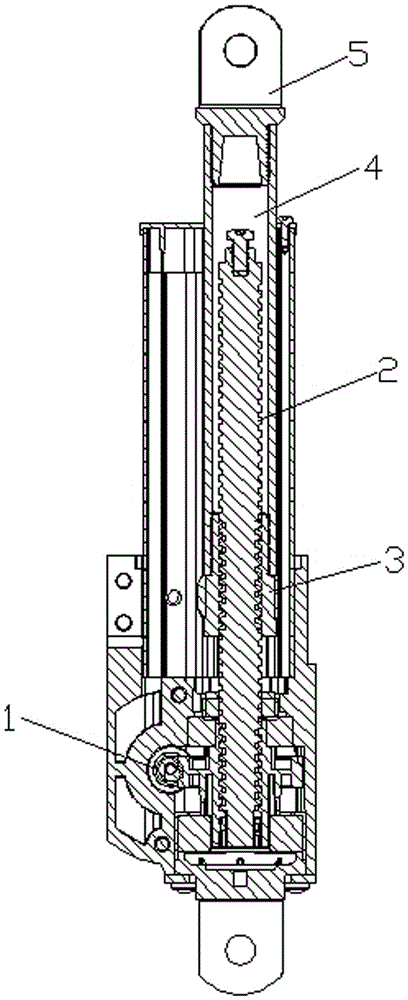
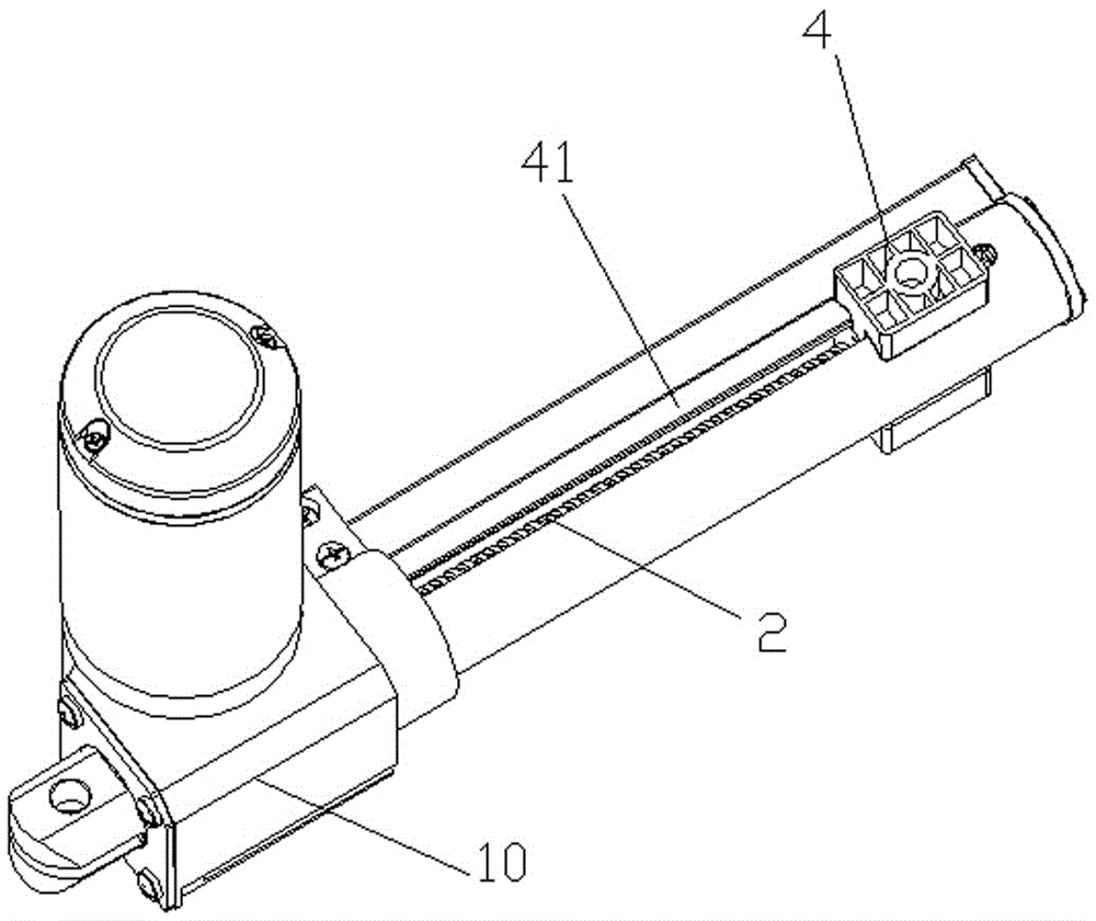
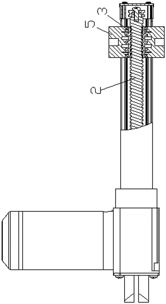
[0017] Such as figure 2 , 3 , 4, a full-stroke lifting worm structure, including a housing 10, a power source located in the housing 10, and a worm 2 driven by the power source to rotate and placed outside the housing 10, the worm 2 jacket A dust-proof outer tube 4 is established, one end of the dust-proof outer tube 4 is fixedly connected to the housing 10, and a limit opening groove 41 is provided on the dust-proof outer tube along its axial direction; A nut 3 is provided, and the nut 3 is connected to the worm screw 2 through threaded engagement. One end of the workbench fixing head...


PUM


Abstract

The invention discloses a total-stroke lifting worm structure which comprises a shell, a power source arranged in the shell and a worm driven by the power source to rotate and arranged outside the shell. The worm is sleeved with an outer dustproof pipe. One end of the outer dustproof pipe is fixedly connected with the shell. A limiting opening groove is formed in the outer dustproof pipe in the axial direction. A nut is further arranged between the worm and the outer dustproof pipe and connected to the worm in a meshed mode through threads. One end of a workbench fixed head is placed in the limiting opening groove of the outer dustproof pipe and fixedly connected with the nut and the workbench fixed head can slide along the limiting opening groove. According to the total-stroke lifting worm structure, the worm and the outer dustproof pipe are used in the total stroke, design waste is avoided, the structure is exquisite, the manufacturing process is relatively exquisite, production cost is reduced to a large extent, and economic benefits are improved to a large extent. In addition, an internal buckling fixing mode is adopted in the structure, so that the risk that the outer dustproof pipe and the nut are separated from each other when a workbench receives extremely large force is greatly avoided, and the stability and the reliability of the structure are improved.

Description

technical field [0001] The invention relates to a lifting worm structure, in particular to a high-precision full-stroke lifting worm structure with a dust-proof outer tube. Background technique [0002] In the lifting mechanism, the lifting worm is often used to adjust the height of the action platform. Currently used lifting worm structures such as figure 1 As shown: the power source 1 drives the worm 2 to rotate, the nut 3 is sleeved outside the worm 2 through threads, one end of the dust-proof outer tube 4 is fixedly sleeved outside the nut 3 through threads, and the fixed head 5 of the workbench is fixed on the dust-proof outer tube 4. At the other end, since the nut 3, the dust-proof outer tube 4 and the workbench fixing head 5 are fixed on the workbench and cannot rotate with the worm, the nut 3, the dust-proof outer tube 4 and the workbench fixing head 5 move along the worm. The axis direction is vertical movement up and down. This structure has the following disad...

Claims


Application Information

Patent Timeline
Patent Type & Authority Patents(China)
IPC IPC(8): F16H37/00F16H57/039F16H25/20
CPCF16H25/20F16H25/2418
Inventor 吴国成
Owner J STAR MOTOR KUSN
Why Eureka
Try Eureka