
Small-flow ultrasonic flowmeter error estimation method based on flow lines

An ultrasonic flowmeter and small flow technology, applied in the direction of liquid/fluid solid measurement, measuring devices, instruments, etc., can solve the problems of increasing the cost of flowmeters, less research on monophonic ultrasonic flowmeters, and measurement errors

Active Publication Date: 2014-07-23
CHONGQING UNIV
View PDF2 Cites 10 Cited by
  • Summary
  • Abstract
  • Description
  • Claims
  • Application Information

AI Technical Summary

Problems solved by technology

This kind of pipeline structure and ultrasonic transducer will disturb the flow field, resulting in measurement errors, which is a key issue in the calibration of small-diameter, small-flow ultrasonic flowmeters
Relevant literature points out that the sags and bulges formed by the ultrasonic transducer near the inner wall of the pipeline distort the flow field, resulting in low measured values. When the sound channel length is 5m, the measured value is 0.05% low. When the sound channel length is At 1m, the measured value is 0.35% lower
However, for small-diameter, low-velocity pipes, the length of the sound channel is generally small, much less than 1m, and the literature does not explain the size of the error
[0003] Summarizing the relevant references, the main shortcomings are as follows: (1) Ultrasonic flowmeters mostly use dual-channel and multi-channel for measurement. On the one hand, the design of the pipeline structure is complex and the installation accuracy is high; tor increases flow meter cost
(2) For low Reynolds number fluids (small flow, small caliber), there are few studies on monophonic ultrasonic flowmeters

Method used

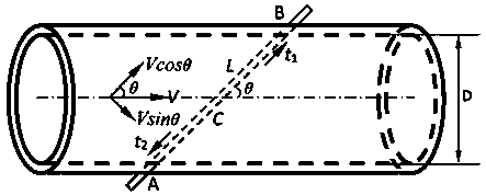

Image

  • Small-flow ultrasonic flowmeter error estimation method based on flow lines
  • Small-flow ultrasonic flowmeter error estimation method based on flow lines
  • Small-flow ultrasonic flowmeter error estimation method based on flow lines

Examples


Embodiment Construction

[0035] The present invention will be described in further detail below in conjunction with the accompanying drawings and specific embodiments.

[0036] A streamline-based error estimation method for a small-flow ultrasonic flowmeter, the method includes the following steps:

[0037] (1) According to the actual structure of the small-diameter, small-flow ultrasonic flowmeter, the simulation analysis and modeling are carried out. The modeling process is as follows:

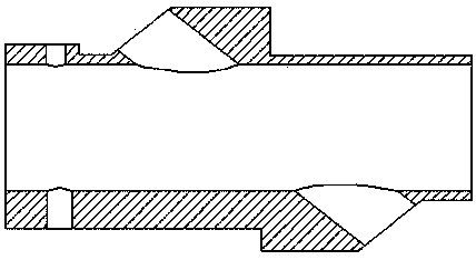
[0038] (a) Use Gambit pre-processing software or 3D CAD software to establish the geometric model of the flowmeter. Pipe inner diameter D , there is a through hole in the direction of 45 degrees to the axis of the pipeline, the transducer is installed, and the pressure and temperature sensors are respectively placed in the upper and lower holes on the left side, for example figure 2 shown.

[0039] (b) Mesh the model. Since the pipeline has a through-hole structure for installing transducers and sensors, the sh...


PUM


Abstract

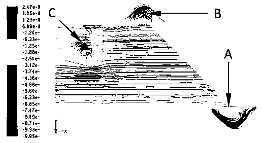
The invention discloses a small-flow ultrasonic flowmeter error estimation method based on flow lines, and belongs to the technical field of ultrasonic flowmeter design and error analysis. The method comprises the steps that a three-dimensional model of a flowmeter is built according to the actual structure of the low-speed micro-flow flowmeter; the flow field distribution of a flow channel is obtained through CFD software, the fluid backflow state and flow line distribution considering the influence of a transducer are generated, and a backflow length is calculated; the metering error of the flowmeter is analyzed according to revised speed difference method power correction factors and a matching expression. The error estimation method for the low-speed micro-flow flowmeter, especially a small-diameter single-track ultrasonic flowmeter, is built on the basis of the fluid mechanics theory and the CFD technology, the expression of the power correction factors is matched, and the foundation is laid for further improving the measuring accuracy of the flowmeter and expanding engineering application.

Description

technical field [0001] The invention belongs to the technical field of ultrasonic flowmeter design, and in particular relates to an error estimation method in the design of a low-speed, small-flow ultrasonic flowmeter. Background technique [0002] Compared with traditional flowmeters, ultrasonic flowmeters have the advantages of no moving parts, no pressure loss, wide measurement range, good repeatability, and high precision, and are widely used in industrial production, especially for pipelines with large diameters and relatively large flows . The ultrasonic flowmeter is mainly composed of ultrasonic transducers, converters and related temperature and pressure sensors installed on the measurement pipeline. Ultrasonic transducers are available in both invasive and non-invasive installations. In non-invasive installation, the signal sent by the ultrasonic transducer needs to penetrate the pipe wall twice, the signal strength is greatly weakened, and the signal-to-noise rat...

Claims


Application Information

Patent Timeline
IPC IPC(8): G01F25/00
Inventor 宋永端高瑞贞沈志熙王磊赖俊峰敖伟
Owner CHONGQING UNIV
Learn More