Supercharge Your Innovation With Domain-Expert AI Agents!

The optical fiber connector

A technology of optical fiber connector and optical fiber, which is applied in the coupling direction of optical waveguide, can solve problems such as alignment deviation, achieve the effect of avoiding damage or scratching, and improving transmission efficiency

Inactive Publication Date: 2017-09-01
SCIENBIZIP CONSULTINGSHENZHENCO
View PDF4 Cites 0 Cited by
  • Summary
  • Abstract
  • Description
  • Claims
  • Application Information

AI Technical Summary

Problems solved by technology

At present, since the optical signal transmission device generally includes a collimator for collimating the optical signal and an optical fiber for transmitting the coupled optical signal, and the photoelectric coupling lens and the optical fiber placement mechanism are usually separate structures, so that the coupling lens and the optical fiber are docked It is easy to cause alignment deviation when

Method used


Image

  • The optical fiber connector
  • The optical fiber connector
  • The optical fiber connector

Examples


Embodiment Construction

[0014] The embodiments of the present invention will be further described in detail below in conjunction with the accompanying drawings.

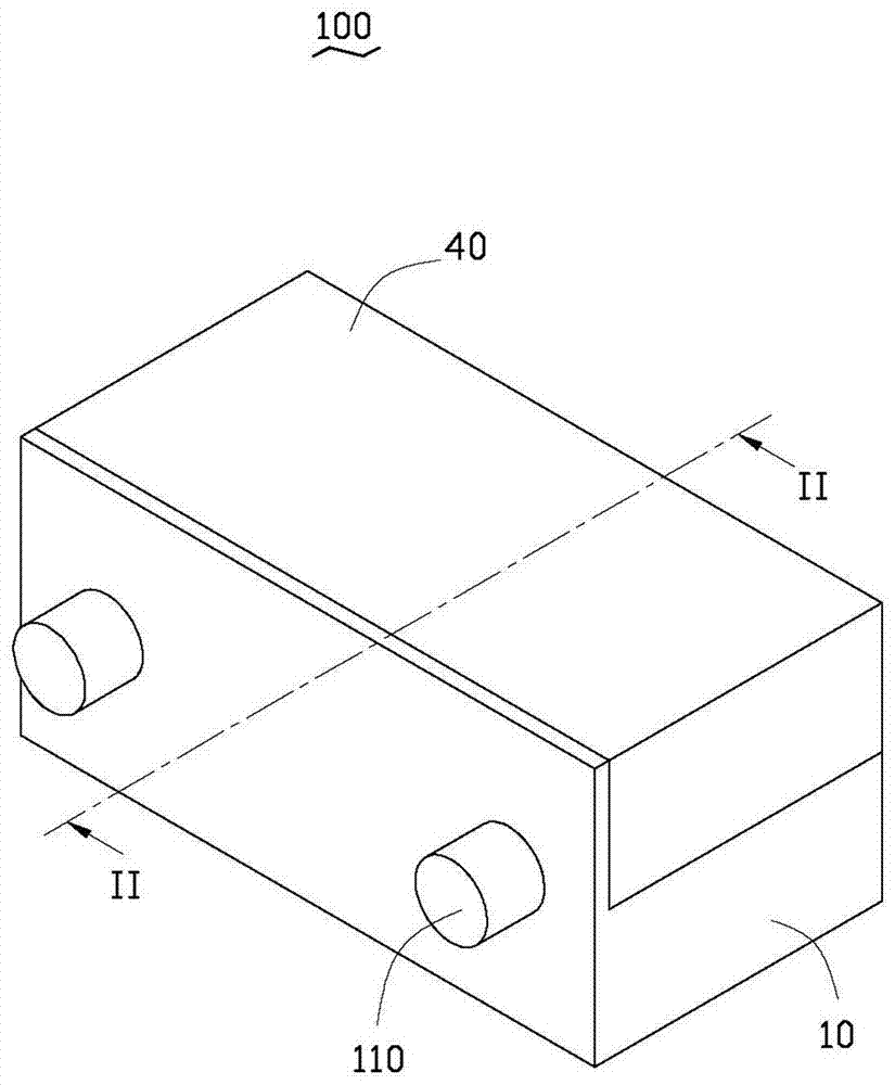
[0015] see Figure 1-4 , an optical fiber connector 100 comprising: a main body 10 , an alignment portion 20 , an optical fiber 30 and a cover 40 .

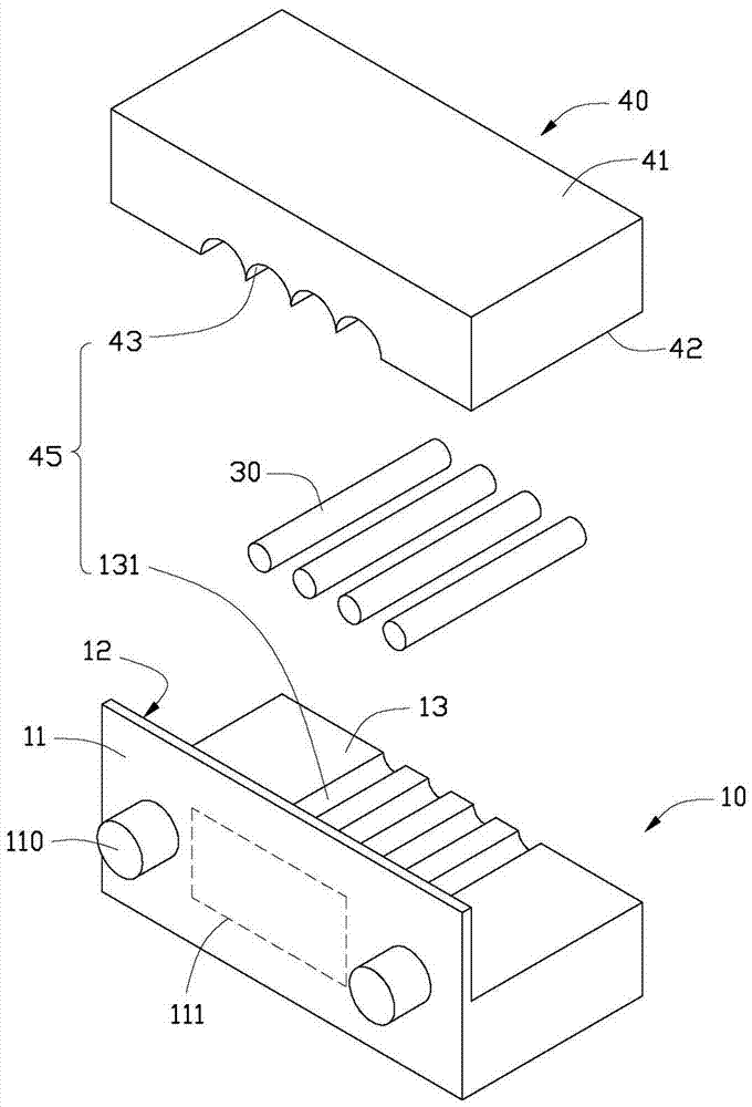
[0016] The main body 10 is L-shaped and includes a mating surface 11 , a mounting surface 12 opposite to the mating surface 11 , and an upper surface 13 perpendicular to the mounting surface 12 .

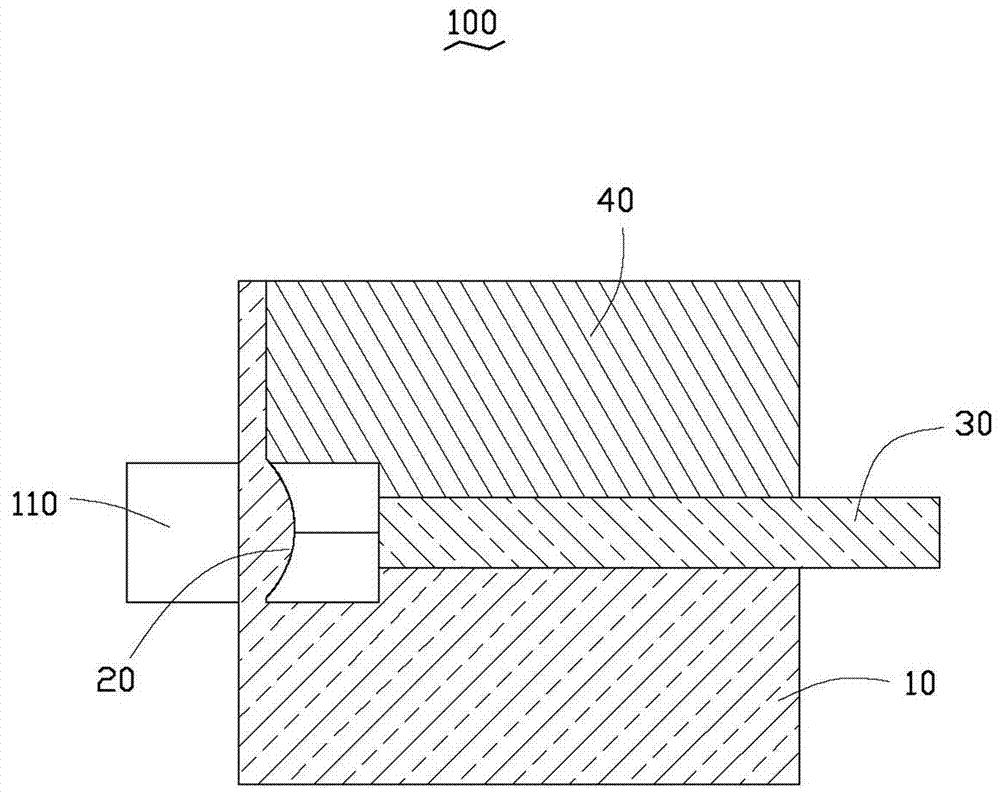
[0017] The docking surface 11 includes a first installation area 111, and the installation surface 12 includes a second installation area 121. The first installation area 111 corresponds to the position of the second installation area 121. In this embodiment, the first installation area Both the area 111 and the second installation area 121 are rectangular. The collimating part 20 is disposed on the second installation area 121 .

[0018] The upper surface 13 defines a receiving groove 131 , and ...


PUM


Abstract

The invention relates to an optical fiber connector, which includes: a main body, a collimation part and an optical fiber; the main body is L-shaped, and includes a butt joint surface, an installation surface opposite to the butt joint surface, and an upper surface perpendicular to the installation surface ; The docking surface includes a first installation area, the installation surface includes a second installation area, the first installation area corresponds to the position of the second installation area, and the alignment part is arranged on the second installation area; the upper surface There is a receiving groove, the axial extension direction of the receiving groove is perpendicular to the installation surface, the receiving groove is aligned with the collimating part, the optical fiber is located in the receiving groove and spaced from the collimating part, and the butt joint surface is spaced apart from two a positioning piece; the first installation area is arranged between the positioning pieces; the main body part, the alignment part and the positioning piece are integrally formed.

Description

technical field [0001] The invention relates to an optical fiber connector. Background technique [0002] In the optical communication system, light is used as the medium of signal transmission, and the higher the integrity of the signal during the signal transmission, the better the transmission system. At present, since the optical signal transmission device generally includes a collimator for collimating the optical signal and an optical fiber for transmitting the coupled optical signal, and the photoelectric coupling lens and the optical fiber placement mechanism are usually separate structures, so that the coupling lens and the optical fiber are docked It is easy to cause alignment deviation. Contents of the invention [0003] In view of this, it is necessary to provide an optical fiber connector that can solve the above problems. [0004] An optical fiber connector, which includes: a main body, a collimation portion, and an optical fiber; the main body is L-shaped,...

Claims


Application Information

Patent Timeline
Patent Type & Authority Patents(China)
IPC IPC(8): G02B6/42
Inventor 洪毅
Owner SCIENBIZIP CONSULTINGSHENZHENCO
Features
  • R&D
  • Intellectual Property
  • Life Sciences
  • Materials
  • Tech Scout
  • Unparalleled Data Quality
  • Higher Quality Content
  • 60% Fewer Hallucinations
Learn More