
Photoelectric coded lock

A combination lock and photoelectric technology, which is applied in the field of photoelectric combination locks, can solve problems such as long unlocking time, inconvenient portability, and delicate operation, and achieve the effects of high security, simple and convenient use, and wide application range

Inactive Publication Date: 2014-07-23
肖守宇
View PDF1 Cites 4 Cited by
  • Summary
  • Abstract
  • Description
  • Claims
  • Application Information

AI Technical Summary

Problems solved by technology

The traditional mechanical combination lock was eliminated because the scale on the turntable was small and difficult to read, and the operation required fine work; the dial-type combination lock was eliminated because it needed to wait for the code to be returned after each dialing, which resulted in a long unlocking time; it is now commonly used The electronic combination lock is considered a great weakness because it cannot be skipped to enter the code, the number of passwords is long and difficult to remember under certain security requirements, and the additional unlocking key is inconvenient to carry, so it is difficult to promote it to home anti-theft doors or normal door use
[0008] 4. It is convenient to set up a password, and the number of passwords needs to be small to be easy to remember, but the security performance cannot be reduced
[0010] What is the standard of a good lock? That is to be able to be widely used in various installation environments, without restricting the user population, anyone can easily operate, fast and convenient to unlock, but it has a high three-proof effect on thieves

Method used


Image

  • Photoelectric coded lock
  • Photoelectric coded lock
  • Photoelectric coded lock

Examples


Embodiment Construction

[0056] In order to more clearly explain the purpose, technical solutions and beneficial effects of the present invention, the present invention will be further described below in conjunction with the accompanying drawings, but the protection scope of the present invention is not limited to the embodiments.

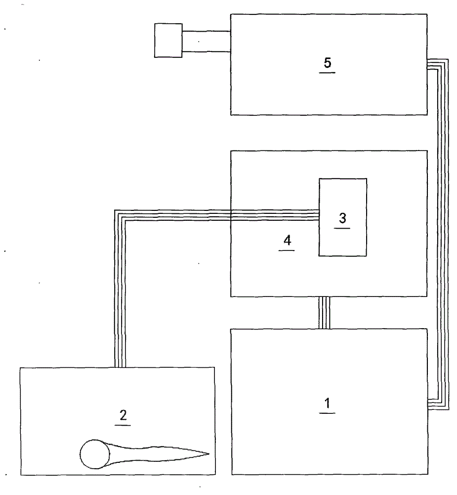
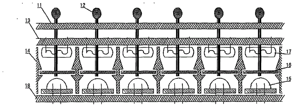
[0057] The present invention is a kind of photoelectric combination lock, which takes "loose association structure, using shallow contact and non-connection mode to transmit password information" as the theoretical guidance, sets the password through the on-off state of the light in the optical channel, and passes the code input The button is associated with the electric key to realize the on-off of the circuit to input and store the password. The circuit is turned on through the light and the light resistance of the photoresistor is suddenly reduced to realize natural decoding. The door lock is opened by manually rotating the door handle, and the whole code, lock, The unlo...


PUM


Abstract

The invention relates to a photoelectric coded lock. The photoelectric coded lock consists of a password setting device, a position varying code inputting device, a position shifting code transmitter, a code storage restorer and a door opening system. The photoelectric coded lock is free from limiting the digital number of a password and free from limiting the password quantity on each digit, and a coded lock with multiple digital numbers and multiple passwords on each digit as well as high safety can be manufactured according to the requirement. The lock is controlled mutually by photo and electricity and integrates a printing circuit, so that the machine is reasonably combined with the electricity, the size is moderate, and the cost is controllable. The lock is simple and convenient for setting the password, the password is short and easy to remember, the lock is easy to operate and fast to unlock, and the locking performance is stable; the lock is a pure digitalized lock, so that the safety is improved compared with the modern coded lock; and the photoelectric coded lock is suitable for different installation environments and different people to use, and can be widely applied to a security door, a safe case, a bank vault, a national security military department, ships, cars and all relatively fixed door cabinets, therefore, the trouble for carrying a key can be thoroughly avoided, and people can enjoy a convenient life brought by the scientific and technological innovation. Once a product of the photoelectric coded lock is issued in the market, a great economic benefit and social benefit can be produced.

Description

technical field [0001] The invention relates to a lock, in particular to a photoelectric combination lock. Background technique [0002] At present, the combination locks commonly used in the market are mainly electronic combination locks. Whether the pure mechanical combination locks are multi-dial type, single dial type or dial type, they are on the verge of being eliminated; recently, a light control Combination lock comes out and goes on the market in local area, is mainly installed on the safe door, but it needs luminous body to make " key ", can not be regarded as real combination lock in fact. The advantage of the electronic combination lock is that it is more convenient to set up the password and unlock, and it is fashionable and popular, but there are also many weaknesses. High, it needs to be accompanied by a key lock for double security; there is no default value in the password, and 0 must be entered as a code, which makes it difficult to remember the password l...

Claims


Application Information

Patent Timeline
IPC IPC(8): G07C9/00
Inventor 肖守宇
Owner 肖守宇
Learn More