
Portable ground fault circuit breaker

A ground fault, circuit breaker technology, applied in the direction of circuit, connection, two-pole connection, etc., can solve the problems of impact, burning electromagnetic tripping device, service life impact, etc.

Inactive Publication Date: 2014-07-23
SHANGHAI YUNYUAN ELECTRICAL APPLIANCE CO LTD
View PDF11 Cites 13 Cited by
  • Summary
  • Abstract
  • Description
  • Claims
  • Application Information

AI Technical Summary

Problems solved by technology

In this way, the burden on the thyristor will be very heavy, not only the service life will be affected, but more importantly, the safety hazard will be aggravated, especially when a short circuit occurs
[0006] The biggest disadvantage of the above-mentioned technology is that the moving contact piece, the static contact piece, the electromagnetic tripping device and the multifunctional protection auxiliary circuit installed on the substrate are all located in a small space. The arc generated when the contacts are closed will definitely affect or even burn the electromagnetic tripping device and multi-function protection auxiliary circuit

Method used


Image

  • Portable ground fault circuit breaker
  • Portable ground fault circuit breaker
  • Portable ground fault circuit breaker

Examples


Embodiment 1

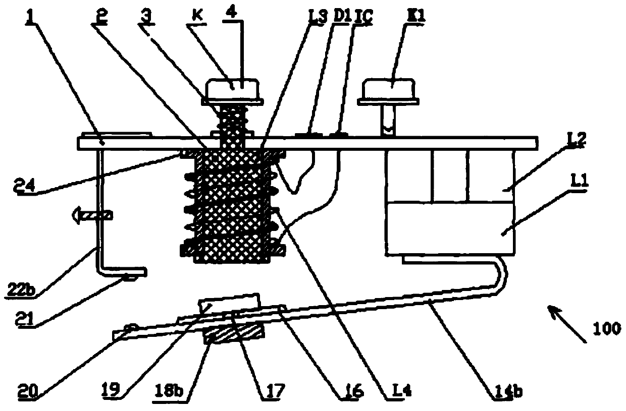
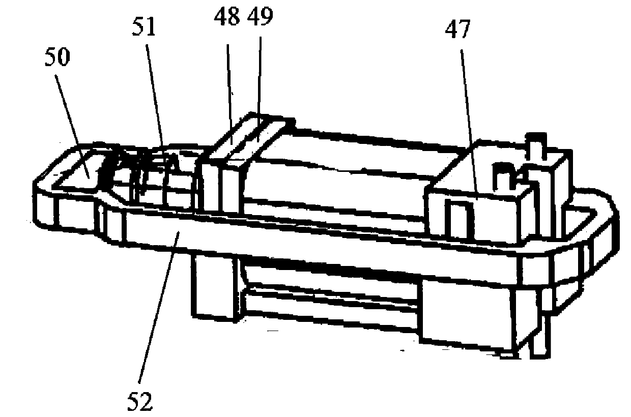
[0058] Embodiment 1, with reference to Figure 3-7 As shown, the portable ground fault circuit breaker includes a main housing 101 , and the main housing 101 is composed of an upper cover 1 , a base 2 and a small bottom cover 3 . Wherein, the base 2 and the small bottom cover 3 are airtightly connected with the upper cover 1 through an annular sealing body 4 , and a button waterproof seal 5 and an indicator light cover 6 are arranged on the top of the upper cover 1 . The end of the upper cover 1 is also provided with a wire seal ring clamping port 8 with a clamping groove 7, and the wire seal ring 9 is clamped in the wire seal ring clamping port 8 by a clamping member 10 arranged thereon, thereby realizing Sealed connections for load leads. A crimping plate 11 is arranged on the inner side of the clamping opening 8 of the wire sealing ring, that is, above the small bottom cover 3, and the crimping plate 11 is fixed inside the upper cover 1 by fasteners, so as to fix the outpu...

Embodiment 2

[0087] Embodiment 2, with reference to Figure 9 As shown, compared with the above-mentioned embodiment 1, this embodiment 2 has no changes in the main structure and principle, so the main description of this embodiment can refer to the above, and the improvement of this embodiment will be described in detail below Where:

[0088] The improvement of this embodiment is that the moving contact frame 26 is mounted on the stop frame 56 through a fixed shaft 57 . That is, the fixed shaft 57 passes through the base cover 22, the movable contact piece 27, and the movable contact frame 26, and its two ends are respectively fixed on the top ends of the stop frames 56 arranged on both sides of the base 21, and The movable contact piece 27 and the movable contact frame 26 are allowed to rotate freely, and the reset button 37 is in contact with the jumper 30 . Pressing reset button 37 can realize switching on easily equally. In this way, the contact spring 25 and the lever fulcrum 24 c...

Embodiment 3

[0089] Embodiment 3, with reference to Figure 10 , 11 As shown, compared with the above-mentioned embodiment 1, this embodiment 2 has no changes in the main structural components, so the structural description of the main components of this embodiment can refer to the above, and the improvement of this embodiment will be described in detail below Where:

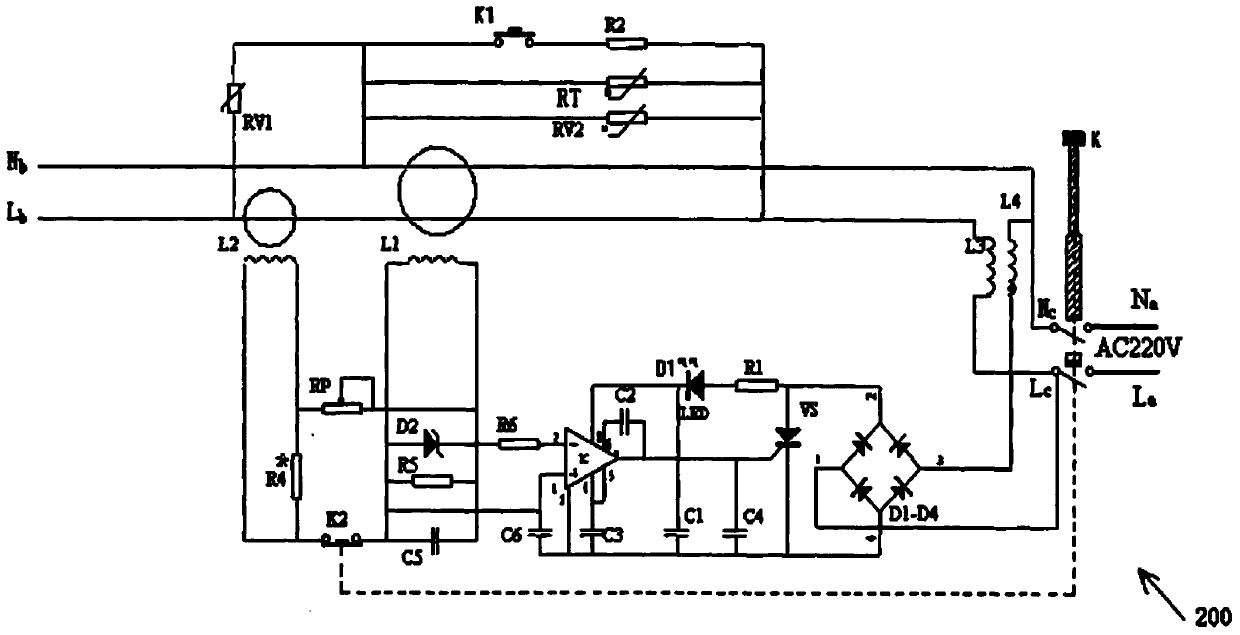
[0090] The improvement of this embodiment is that: the circuit board 13 is provided with a peripheral circuit A, a test circuit B, a power switch circuit C, a working instruction circuit D, a detection induction circuit E, a main control circuit F, and a signal amplification circuit G, wherein, The detection induction circuit E is provided with an electric leakage electric shock ground fault detection induction circuit E1 and a neutral ground fault detection circuit E2, but the short circuit detection circuit E3 is not provided; the main control circuit F is provided with a leakage electric shock ground fault control circui...


PUM


Abstract

The invention relates to a portable ground fault circuit breaker comprising a main shell. The portable ground fault circuit breaker is characterized by further comprising an internal shell which is arranged in the main shell and composed of a pedestal and a base cover. The internal shell is internally provided with a moving contact and a static contact. The static contact is suspended in the internal shell. The moving contact is arranged on an imbalance moving contact frame. One end of the moving contact frame is provided with a jump buckle which is connected with a lock buckle enabling the moving contact and the static contact to be switched and closed. The lower end of the lock buckle penetrates through the pedestal to be contacted with an electromagnetic trip mechanism which is arranged on the external bottom of the pedestal. The electromagnetic trip mechanism is electrically connected with a main control circuit which is arranged on a circuit board. The beneficial effects are that the portable ground fault circuit breaker is simple in structure, small in volume and convenient to use, and the outline is designed as a human body. Meanwhile, the portable ground fault circuit breaker has load side electric leakage, electric shock, ground fault and neutral wire ground fault protection functions and a short circuit protection function so that a load side phase wire and the neutral wire can be disconnected simultaneously. Besides, the portable ground fault circuit breaker has a waterproof protection function and is long in the service life so that electric spark is not generated and heat is not liable to generate.

Description

technical field [0001] The invention relates to the technical field of electrical equipment protection devices, in particular to a portable ground fault circuit breaker that can automatically break the load-side power supply in the event of short circuit, leakage, electric shock, ground fault and neutral ground fault, and has protection functions such as waterproof. Background technique [0002] Recently, fires caused by electrical short-circuits have occurred frequently, causing serious losses to people's lives and property. With the further development of science and technology, people began to design and use some devices for the protection of electrical appliances and equipment. Most of the various protection devices do not have the short-circuit protection function, or have the short-circuit protection function because the structure is not reasonable enough, such as not having the arc extinguishing function, and electric sparks are generated when the switch is closed, wh...

Claims


Application Information

Patent Timeline
Patent Type & Authority Applications(China)
IPC IPC(8): H01H71/10H01H71/24H01H83/00
CPCH01H83/144H01H71/24H01R13/7135H01R24/30H01R2103/00H02H3/105H02H3/331
Inventor 刘国久薛建国严永煊
Owner SHANGHAI YUNYUAN ELECTRICAL APPLIANCE CO LTD
Learn More