A method and device for determining a target cell
A target cell and cell technology, applied in the field of communication, can solve the problems of increasing handover preparation delay, reducing user experience, dropped calls, etc., to achieve the effect of reducing handover preparation delay, improving user experience, and improving handover performance
- Summary
- Abstract
- Description
- Claims
- Application Information
AI Technical Summary
Problems solved by technology
Method used
Image

Examples
Embodiment 1
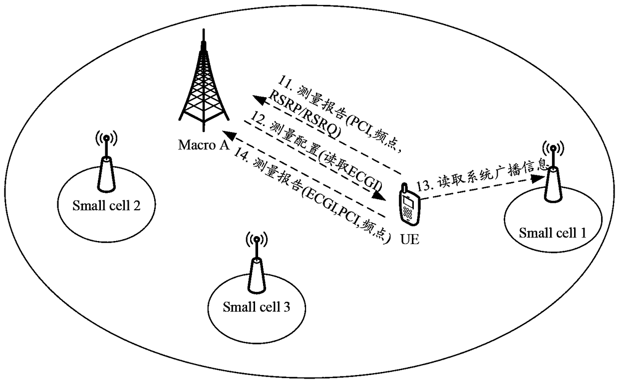
[0093] Embodiment 1. Assume that 5 small cells are deployed within the coverage of macro cell A (macro cell A), that is, smallcell1~small cell5. For the network topology, see Figure 5 As shown, small cell1 and small cell3 have the same operating frequency and PCI, and the PCIs of other small cells are different. In this embodiment, each base station adopts method 1 to obtain the first location information of each cell controlled by itself, and the second location information is the longitude and latitude information of the location of the UE; for the process of determining the target cell by the macro base station provided in this embodiment, see Image 6 shown, including the following steps:
[0094] Step 61. The macro base station A obtains the first location information of each cell controlled by itself, and the small base station obtains the first location information of each cell controlled by itself;
[0095] Specifically, when deploying macro base station A (that is, ...
Embodiment 2
[0112] Embodiment 2, still with Figure 5 The network topology shown is taken as an example. This embodiment is similar to Embodiment 1. The difference is that in this embodiment, macro base station A adopts method 1 to obtain the first location information of each cell controlled by itself, and the macro base station A Each adjacent small base station acquires the first location information of each cell controlled by itself in mode 2;
[0113] Specifically, when the operator deploys macro base station A (that is, the base station where macro cell A is located), the operator configures the first location information of macro cell A; each small base station obtains the location information of the small cell it controls through its own positioning device. First location information.
Embodiment 3
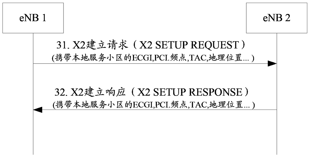
[0114] Embodiment 3, still with Figure 5 The network topology shown is taken as an example. In this embodiment, small eNB1 has established an interface connection (such as X2 interface) with macro base station A, and then the serving cell small cell1 of small eNB1 changes its own configuration information (such as PCI, and changes The following PCI is exactly the same as the PCI of small cell3); in this embodiment, the macro base station determines the process of the target cell, see Figure 7 shown, including the following steps:
[0115] Step 71, small eNB1 sends an interface signaling message to macro base station A, and the interface signaling message carries the updated configuration information of smallcell1;
[0116] Wherein, the configuration information includes configuration parameters (the configuration parameters include operating frequency points and PCI, ECGI, TAC, etc.) and first location information;
[0117] Step 72: After receiving the interface signaling ...
PUM
 Abstract
Description
Claims
Application Information
 - R&D
- Intellectual Property
- Life Sciences
- Materials
- Tech Scout
- Unparalleled Data Quality
- Higher Quality Content
- 60% Fewer Hallucinations
Browse by: Latest US Patents, China's latest patents, Technical Efficacy Thesaurus, Application Domain, Technology Topic, Popular Technical Reports.
© 2025 PatSnap. All rights reserved.Legal|Privacy policy|Modern Slavery Act Transparency Statement|Sitemap|About US| Contact US: help@patsnap.com