Pump element of a hydraulic unit for a vehicle brake system

A technology of hydraulic equipment and brake fluid, which is applied in the field of pump components, can solve problems such as component damage, and achieve the effects of uniform volume delivery, uniform volume flow, and uniform fluid volume flow

Inactive Publication Date: 2014-07-23
ROBERT BOSCH GMBH
View PDF5 Cites 0 Cited by
  • Summary
  • Abstract
  • Description
  • Claims
  • Application Information

AI Technical Summary

Problems solved by technology

On the other hand, pressure peaks associated with pressure pulses are the cause of component damage

Method used


Image

  • Pump element of a hydraulic unit for a vehicle brake system
  • Pump element of a hydraulic unit for a vehicle brake system
  • Pump element of a hydraulic unit for a vehicle brake system

Examples


Embodiment Construction

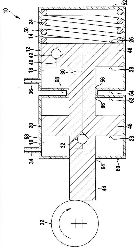
[0028] exist figure 1 A pump element 10 of a hydraulic system (not shown in further detail) of a vehicle brake system for supplying brake fluid is shown in . The pump element 10 includes a cylinder 12 with a first cylinder chamber 14 , a second cylinder chamber 16 and a suction chamber 18 .

[0029] Furthermore, the pump element 10 comprises a piston 20 mounted reciprocally displaceably in the cylinder 12 . For displacement, the pistons 20 are each coupled on one end side thereof to an eccentric 22 and on the opposite end side to a return spring 24 in a pressure-transmitting manner. Furthermore, the piston 20 has a first active surface 26 in the first cylinder chamber 14 and a second active surface 28 in the second cylinder chamber 16 .

[0030] The second cylinder chamber 16 is connected to the first cylinder chamber 14 via a first line 30 , which here leads through the piston 20 and has an associated non-return valve 32 . Furthermore, a pressure line 34 for discharging t...


PUM


Abstract

In a pump element (10) of a hydraulic unit for a vehicle brake system for delivering brake fluid by means of a piston (20) mounted so as to reciprocate in a cylinder (12), the piston (20) has a first and a second active surface (26, 28) of which the first active surface (26) causes brake fluid to be delivered from the cylinder (12) during the forward movement of the piston (20) and the second active surface causes brake fluid to be delivered from the cylinder (12) during the backward movement of the piston (20).

Description

technical field [0001] The invention relates to a pump element of a hydraulic system of a vehicle brake system, which is used for delivering brake fluid and has a reciprocatingly mounted piston in a cylinder. Background technique [0002] Pump elements of the type described here are also referred to as vehicle brake system piston pumps and have a reciprocating piston, which is usually driven by means of an eccentric. Such pump elements, which are used, for example, in systems with an electronic stability program (ESP), fundamentally have a delivery volume of fluid, in particular brake fluid, that varies strongly over time per unit of time. This temporally very inhomogeneous curve of the delivery volume is present on the suction side of the pump element, but in particular also on the pressure side of the pump element, and here likewise leads to pressure pulses. On the one hand, the pressure pulses cause disturbing noises, which are referred to as noise, vibration, harshness ...

Claims


Application Information

Patent Timeline
Patent Type & Authority Applications(China)
IPC IPC(8): B60T8/40F04B5/02
CPCB60T8/4031F04B5/02F04B3/003
Inventor I·布亨奥
Owner ROBERT BOSCH GMBH
Why Eureka
Try Eureka