Hybrid-vehicle control device
A hybrid vehicle and control device technology, which is applied to hybrid vehicles, power devices, control devices, etc., can solve problems such as reduced driving force and reduced engine output.
- Summary
- Abstract
- Description
- Claims
- Application Information
AI Technical Summary
Problems solved by technology
Method used
Image

Examples
no. 1 Embodiment approach
[0031] Below, refer to Figure 1 to Figure 5 , the first embodiment in which the control device for a hybrid vehicle according to the present invention is embodied will be described in detail.
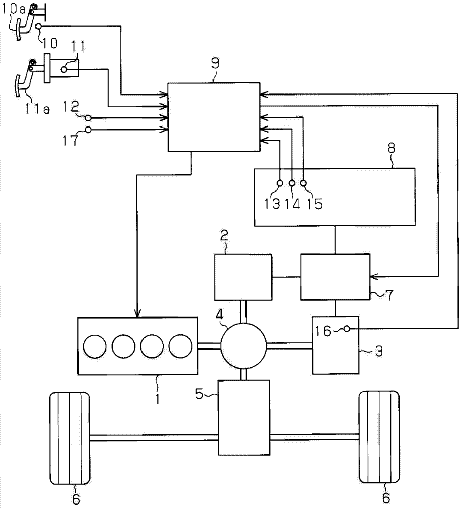
[0032] First, refer to figure 1 , the configuration of a hybrid system of a hybrid vehicle to which the control device of the present embodiment is applied will be described.
[0033] This hybrid system includes an engine 1 as a heat engine and two motor generators. Hereinafter, the motor generator mainly used for power generation is referred to as generator 2 , and the motor generator mainly used for generating driving force is referred to as motor 3 .
[0034] The engine 1, the generator 2, and the motor 3 are connected to a power distribution mechanism 4 including planetary gears. In addition, the power distribution mechanism 4 is also connected to the drive wheels 6 via the reduction mechanism 5 . Further, the power of the engine 1 is divided into power for driving the generato...
no. 2 Embodiment approach
[0060] Next, also refer to Image 6 with Figure 7 , a second embodiment in which the control device for a hybrid vehicle according to the present invention is embodied will be described in detail. In addition, in the present embodiment and each of the embodiments described later, the same reference numerals are assigned to the same configurations and functions as those of the above-mentioned embodiments, and detailed description thereof will be omitted.
[0061] In the first embodiment, by maintaining the engine torque when the brake priority system is activated, the deterioration of the re-acceleration performance of the hybrid vehicle after the system is released is suppressed. In the present embodiment, when the brake priority system is activated, the engine torque is increased in advance for the reacceleration performance of the hybrid vehicle after the brake priority system is released, thereby ensuring higher reacceleration performance.
[0062] In this embodiment, by...
no. 3 Embodiment approach
[0072] Next, also refer to Figure 8 with Figure 9 , a third embodiment in which the control device for a hybrid vehicle according to the present invention is embodied will be described in detail.
[0073] During the motor running of the hybrid vehicle with the engine 1 stopped, when the brake priority system is activated, if the accelerator pedal 10a is further depressed after the brake pedal 11a is released, the output of the motor 3 alone may not be able to To ensure the HVS output requested by the driver, it is necessary to start the engine 1 . In such a case, the increase in the output of the HVS delays the time required to start the engine 1, and thus the re-acceleration performance of the hybrid vehicle deteriorates. Therefore, in the present embodiment, the engine 1 is started in advance when the brake priority system is activated, thereby improving the re-acceleration performance of the hybrid vehicle after it is released.
[0074] In this embodiment, by Figure ...
PUM
 Abstract
Description
Claims
Application Information
 - R&D
- Intellectual Property
- Life Sciences
- Materials
- Tech Scout
- Unparalleled Data Quality
- Higher Quality Content
- 60% Fewer Hallucinations
Browse by: Latest US Patents, China's latest patents, Technical Efficacy Thesaurus, Application Domain, Technology Topic, Popular Technical Reports.
© 2025 PatSnap. All rights reserved.Legal|Privacy policy|Modern Slavery Act Transparency Statement|Sitemap|About US| Contact US: help@patsnap.com