Eureka AIR delivers breakthrough ideas for toughest innovation challenges, trusted by R&D personnel around the world.

Automatic transmission controls

A technology of automatic transmission and control device, applied in the direction of transmission device, fluid transmission device, transmission device control, etc., can solve the problems of violating the idle driving feeling, slow shifting, etc., and achieve the effect of suppressing the impact of shifting, avoiding the slowness and the feeling of idle driving.

Active Publication Date: 2016-01-27
JATCO LTD +1
View PDF9 Cites 0 Cited by
  • Summary
  • Abstract
  • Description
  • Claims
  • Application Information

AI Technical Summary

Problems solved by technology

In this case, since the engine torque appears during the shift, there will be a problem of slow shifting, and especially in the case of shifting in the high-rotation range, it will take time to shift, so there will be a driver's disobedience. new problem

Method used


Image

  • Automatic transmission controls
  • Automatic transmission controls
  • Automatic transmission controls

Examples


Embodiment 1

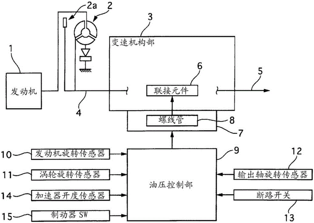
[0015] figure 1 It is a schematic diagram showing the system configuration of the automatic transmission of the first embodiment. An engine 1 is connected to a transmission mechanism unit 3 of an automatic transmission via a torque converter 2 . The engine 1 increases or decreases the output through the throttle valve whose opening increases from fully closed to fully open in conjunction with the accelerator pedal operated by the driver. The output rotation of the engine 1 passes through the torque converter 2 and is input to the transmission mechanism 3 input shaft 4. The torque converter 2 employs a well-known configuration having a function of amplifying the output torque of the engine 1 by generating a difference between input and output rotational speeds. In addition, the torque converter 2 is provided with a lock-up clutch 2a that can suppress the difference in input and output rotational speeds, in other words, can suppress the torque amplification effect, and can dir...


PUM


Abstract

A control device for an automatic transmission that improves shift shock regardless of the driver's accelerator pedal operation. The control device of the automatic transmission includes: a torque converter and a lock-up clutch interposed between the engine and the automatic transmission; When an upshift is performed with the accelerator pedal depressed, the engaging capacity of the engaging element on the release side, which engages at the shift stage before shifting, is decreased, and the engaging capacity of the engaging element, which is engaged at the shift stage after shifting, is increased. Therefore, a shift is performed, wherein when the accelerator pedal is lifted during the power-on upshift, the upshift control device lowers the engagement capacity of the lock-up clutch to continue the power-on upshift. Pass upshift.

Description

technical field [0001] The invention relates to a speed change control during upshifting of an automatic transmission. Background technique [0002] Conventionally, as described in Patent Document 1, when an upshift is performed with the driver depressing the accelerator pedal (hereinafter referred to as a power-on upshift), the inertia of the gear ratio actually changes. In the stage, the inertia stage occurs due to the clutch capacity on the engaging side, and the gear change is performed. On the other hand, when an upshift is performed with the driver lifting the accelerator pedal (hereinafter referred to as a power off upshift), since the engine torque is low, the output torque after the upshift becomes small. Therefore, by controlling the output torque in the inertia phase to be as low as possible, the purpose is to suppress the torque step difference (shock) at the end of the inertia phase. Therefore, not only the torque capacity on the coupling side in the inertia p...

Claims


Application Information

Patent Timeline
Patent Type & Authority Patents(China)
IPC IPC(8): F16H61/04F16H61/14
CPCF16H61/061F16H61/143F16H61/684F16H59/18F16H2061/146F16H2061/0492B60W10/02B60W10/023B60W10/11
Inventor 岩本育弘
Owner JATCO LTD
Why Eureka
Eureka Blog
Learn More