Electrode foil cutting device and method

A technology of cutting device and cutting method, which is applied in the direction of electrode manufacturing, battery electrodes, electrode carriers/collectors, etc., can solve the problems of speed change, poor quality, and difficult realization of mechanical devices, and achieve stable operation, excellent processing quality, and improved The effect of processing quality

Active Publication Date: 2016-12-21
ケーラボエルティーディー
View PDF3 Cites 0 Cited by
  • Summary
  • Abstract
  • Description
  • Claims
  • Application Information

AI Technical Summary

Problems solved by technology

[0011] However, when the scanner is driven at high speed, constant quality can be ensured in the straight section, but there is a disadvantage that the faster the speed, the worse the quality is in the corner section of the vertex portion of the quadrangle
The biggest problem is that the speed of the workbench changes sharply when it passes a straight line corner. This kind of sharp speed change is difficult for mechanical devices, and it is difficult to reach the speed of 60m / min in a short time.

Method used


Image

  • Electrode foil cutting device and method
  • Electrode foil cutting device and method
  • Electrode foil cutting device and method

Examples


Embodiment Construction

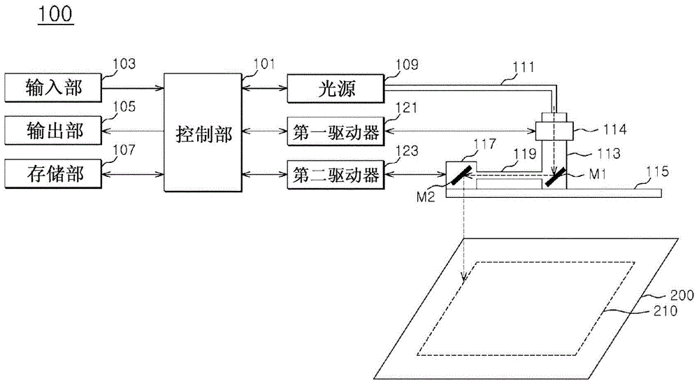
[0027] An electrode foil cutting device according to an embodiment of the present invention may include: a rotating body arranged horizontally and vertically at a prescribed distance from the workbench; a rotating shaft arranged at the center of the rotating body and driven by a first driver so that The rotating body rotates at a predetermined moving speed; and the scanner is installed at one end of the rotating body, and moves to the above-mentioned processing according to the rotation angle of the rotating body, the moving speed, and the speed change rate based on the processing size of the object to be processed. The above-mentioned processed portion of the object is irradiated with a laser beam.

[0028] Hereinafter, embodiments of the present invention will be described more specifically with reference to the drawings.

[0029] figure 2 It is a structural diagram of an electrode foil cutting device according to an embodiment of the present invention.

[0030] refer to ...


PUM


Abstract

The present invention provides an electrode foil cutting device and method. The above-mentioned electrode foil cutting device comprises: a rotating body arranged horizontally and vertically at a predetermined distance from the worktable; a rotating shaft arranged at the center of the rotating body, driven by a first driver Drive to rotate the rotating body at a prescribed speed; and the scanner is installed at one end of the rotating body and scans the laser beam according to the rotation angle of the rotating body, the moving speed, and the speed change rate based on the processing size of the object to be processed. Irradiate the processed part of the object to be processed.

Description

technical field [0001] The present invention relates to a cutting device and method, more particularly to an electrode foil cutting device and method. Background technique [0002] With the increasing interest in electric vehicles around the world and the intensification of research and development competition, it can be predicted that related industries will also grow significantly, especially the secondary battery market will become the center. [0003] Electric vehicles started with hybrid HEV (Hybrid Electric Vehicle; hybrid electric vehicle), and are developing into PHEV (Plug in Hybrid Electric Vehicle; plug-in hybrid electric vehicle) and EV (Electric Vehicle; pure electric vehicle). In addition, the reality is that the research and development of batteries as a power source is the main focus of the electric vehicle market, and battery companies are doing their best to preempt new technologies. [0004] Under such a realistic background, in the secondary battery indu...

Claims


Application Information

Patent Timeline
Patent Type & Authority Patents(China)
IPC IPC(8): H01M4/04H01M4/64B26D5/00
CPCB26D5/00H01M4/04H01M4/64Y02E60/10Y02P70/50H01M4/62H01M10/052
Inventor 韩裕熙权九彻
Owner ケーラボエルティーディー
Why Eureka
Try Eureka